August 9, 2026
With SMT line efficiency and material cost squeezed tighter every year, panelization — the step so often handed off to the fab — is actually an underrated cost lever in the engineer's own hands. Most R&D engineers finish the single board and ship it straight out, rarely stopping to weigh V-Cut versus mouse bite versus tab routing. Yet that one choice drives material utilization, post-separation edge quality, the mechanical stress on components, and even whether the SMT machine can grip the panel at all. This article lays out the rules, limits, and trade-offs of V-Cut panelization from a manufacturing point of view.
Choosing a panelization method is fundamentally a trade‑off among cost, edge quality, and mechanical stress. V‑Cut gives the highest material utilisation and the lowest cost, but only in straight lines and with more stress on components; mouse bite handles irregular shapes with low separation stress but lower utilisation; tab routing delivers the cleanest edges and the least stress, but is the most expensive and slowest. None is absolutely better than the others — there's only "right or wrong for your board shape and volume." Settling the panelization approach at the design stage, rather than leaving the fab to guess, often saves material, labour, and the risk of breakage during separation in one move.
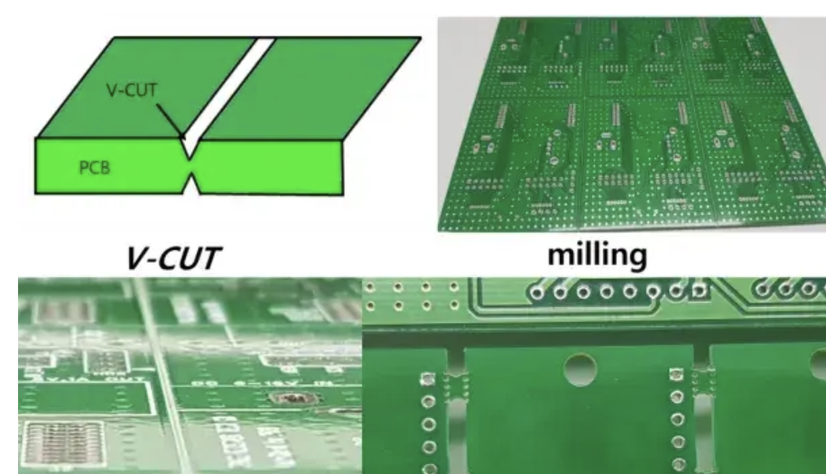
V‑Cut (V‑scoring) is the most efficient way to panelise regular rectangular boards, but its physics also set its ceiling. The process cuts a V‑groove on both the top and bottom along the board edges, leaving about one‑third of the board thickness as a connecting web — keeping the panel rigid during SMT while letting you snap the boards apart by hand afterward. Minor fibre residue often remains after separation and scrapes off easily. Because the material expands and tears during separation, V‑Cut boards carry a slightly larger dimensional tolerance of about ±0.4 mm.
Its limits are equally clear: straight lines only — no curves or irregular shapes; double‑sided scoring only, never single‑sided; and 0.4 mm‑thin boards don't support V‑Cut (generally ≥0.6 mm is required). Separation also imposes higher mechanical stress, so components and traces near the score line need adequate clearance or they can be damaged during depaneling.

Commit the following hard parameters to memory and you'll avoid ninety percent of V‑Cut rejections and engineering back‑and‑forth.
| Parameter | Specification | Notes | | :--- | :--- | :--- | | V‑score angle | 25° | Double‑sided, symmetric top/bottom | | Min panel size | 70 × 70 mm | Both length and width ≥70 mm | | Max panel size | 475 × 475 mm | When both H and V cuts are used | | Copper/trace to score line | ≥0.4 mm (1.0 mm recommended) | To V‑Cut centreline; ≥2.0 mm for tall components | | Min connecting edge width | 3 mm (5 mm for ≤0.8 mm thick) | — | | Thickness restriction | Not for 0.4 mm | Generally ≥0.6 mm |
Also note: regular V‑Cut has zero gap between boards, so material utilisation often exceeds 90% — precisely why it's the cheapest method. But watch out: where a V‑score line meets a routed slot, the circular milling tool can leave a small protruding sharp corner after separation. Add a 3–5 mm process edge (tab) between boards so the tool can pass fully and cut a clean edge.
Panelisation isn't just cutting — it also has to account for whether the SMT line can handle the panel. A few of the most‑overlooked points:
Spending a few minutes marking these clearly on the panel drawing saves a lot of back‑and‑forth on the line.
Choosing the right method means stacking four things together: board shape, volume, edge requirements, and stress sensitivity. Mouse bite connects boards with a set of small holes (commonly 0.60 mm, 5–8 per set) and narrow tabs — good for irregular, L‑shaped, or curved boards, with low separation stress and components allowed closer to the edge, but it needs 1.6–2 mm between boards, gives lower utilisation, and leaves slightly serrated edges at the tabs. Tab routing uses CNC to mill away most of the outline, leaving wider tabs — best edge quality and precision, least stress, often paired with mouse bites — but highest cost, longest processing time, and more material waste.
 | Criteria | V‑Cut | Mouse Bite | Tab Routing |
| :--- | :--- | :--- | :--- |
| Board shape | Rectangular, straight edges only | Any / irregular | Any / irregular |
| Material utilisation | Excellent (zero gap) | Good (1.6–2 mm gap) | Moderate |
| Edge after separation | Good (minor fibres) | Fair (serrated tabs) | Excellent |
| Mechanical stress | Higher | Low | Lowest |
| Cost | Lowest | Moderate | Highest |
| Best for | High‑volume rectangular | Irregular / cost‑saving SMT | Fragile boards / strict edges |
| Criteria | V‑Cut | Mouse Bite | Tab Routing |
| :--- | :--- | :--- | :--- |
| Board shape | Rectangular, straight edges only | Any / irregular | Any / irregular |
| Material utilisation | Excellent (zero gap) | Good (1.6–2 mm gap) | Moderate |
| Edge after separation | Good (minor fibres) | Fair (serrated tabs) | Excellent |
| Mechanical stress | Higher | Low | Lowest |
| Cost | Lowest | Moderate | Highest |
| Best for | High‑volume rectangular | Irregular / cost‑saving SMT | Fragile boards / strict edges |
When needed, hybrid panelisation — V‑Cut on some axes, mouse bite on the rest — balances utilisation against shape flexibility.
V‑Cut's high utilisation and low cost are all but irreplaceable for regular rectangular boards; but the moment the shape turns irregular, components become stress‑sensitive, or edge quality gets strict, mouse bite and tab routing are the right answers. Keeping this decision at the design stage — rather than leaving the fab to guess — saves material, labour, and the risk of separation breakage all at once. One last critical step: after the panel is finalised, always build your stencil and fixtures from the fab's returned engineering files (not your original Gerbers), so that stencil, fixtures, and the actual panel line up exactly.
eCloud brings deep DFM experience in both rectangular and irregular panelisation and in SMT‑compatible design. Is your next project heading into panelisation and mass production? Reach out to our engineering team at the design stage for a DFM review of your panel and SMT setup, and optimise material utilisation and separation yield in one pass.
