July 18, 2026
For hardware teams, even the best-designed board ultimately has to live inside a mechanical part — and sheet metal bending is the workhorse process behind communication cabinets, industrial enclosures, and medical equipment housings. Bending looks like the simplest forming process there is, yet production problems like cracking, hole distortion, tooling interference, excessive springback, and assembly failures almost always trace back to the design stage. This article organizes the core principles of sheet metal bending and the 5 most critical DFM rules, so engineers can retire manufacturing risk while the CAD file is still open.
 Modern sheet metal fabrication relies on three primary bending methods, each trading precision, cost, and efficiency differently:
| Comparison | Air Bending | Bottoming | Coining | | :--- | :--- | :--- | :--- | | Principle | Sheet contacts punch and die only at points; angle controlled by penetration depth | Sheet pressed fully into the die cavity | Extreme pressure plastically deforms the bend line | | Precision | Moderate | Higher | Highest | | Springback | Larger | Reduced | Virtually eliminated | | Cost | Low, low tooling wear | Higher tonnage required | High tooling wear, lower throughput |
General structural parts do fine with air bending; reserve bottoming for features with tight angular consistency requirements, and coining only for extreme‑precision features — never the whole part.
The inside bend radius is the single most critical parameter in bending design. Too small, and the outer fibres overstretch and crack; too large, and springback and dimensional variation grow. The baseline practice is to select the recommended minimum inside radius for the material thickness T — and keep it consistent across the part.
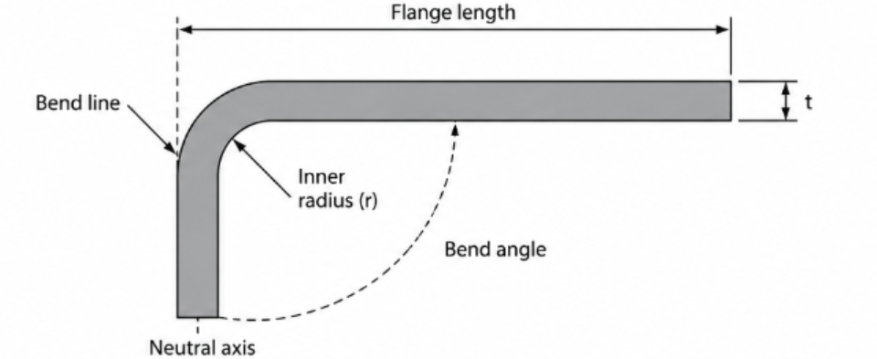
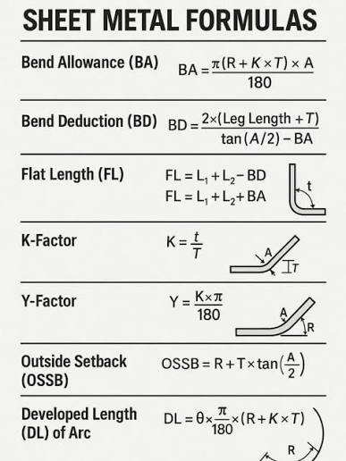
During bending, the inner surface compresses while the outer surface stretches; between them lies the neutral axis, which does neither. Its position shifts with material, thickness, and bend radius — which is exactly why flat patterns come out wrong. Three parameters derive from it: the K‑factor (position of the neutral axis within the thickness), Bend Allowance (length of the neutral axis through the bend region), and Bend Deduction (difference between theoretical flat and finished bent dimensions). Bend allowance is calculated as:
BA = θ × (R + K × T) × π / 180
where θ is the bend angle, R the inside radius, K the K‑factor, and T the thickness. An incorrect flat pattern is the most common reason a sheet metal prototype fails on the first pass.
Holes, slots, and cutouts placed too close to a bend line are the most common design mistake — stress concentration during bending distorts holes, tears material, or throws dimensions. Keep hole edges at least 4T from the bend line and hole distortion essentially disappears.
A flange that's too short can't be supported by standard press brake tooling, leading to incomplete forming or angular error.
Bends placed too close together cause tooling interference — beyond the collision risk, they complicate bend sequencing and inflate setup time.
Reverse bends with insufficient offset often demand special tooling and multiple setups; open up the offset wherever possible and cut cumulative tolerance error.
Corner intersections without reliefs concentrate stress and cause tearing or warping. Rectangular reliefs are the easiest to make and most widely used; round reliefs distribute stress better and suit cosmetic and precision parts.
| Defect | Root cause | | :--- | :--- | | Cracking | Bend radius too small, grain direction parallel to the bend line, or burrs and micro‑cracks on the material edge | | Springback | Elastic recovery after forming — stainless steel shows the most, aluminium moderate, mild steel the least; countermeasures include overbending, bottoming, and optimised radius selection | | Hole distortion | Almost always a feature too close to the bend line — back to the 4T rule | | Surface scratches | Tool friction, unprotected surfaces, or damaged tooling; protective films and polished tooling markedly improve cosmetic quality |
None of these habits costs any functionality, but all of them show up directly in the quote and the lead time.
The essence of good bending design is understanding material behaviour and following proven manufacturing rules — most defects, overruns, and delays are preventable at the design stage with proper DFM. For hardware teams there is a second layer: the enclosure's bend structure dictates the PCB's board outline, mounting holes, and connector openings, and a late mechanical freeze means the board changes with it.
In our PCB DFM pre‑reviews and PCBA project coordination, board outline and assembly interfaces are always among the first items to align — the earlier mechanical and electrical converge, the cheaper every downstream change becomes. Still converging board shape and enclosure on your next project? Talk to our engineering team and lock the PCB‑side DFM constraints early.
