June 8, 2026
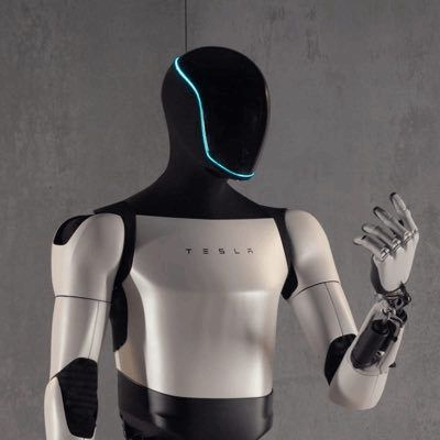
Humanoid robots have been a hot topic lately, from Tesla’s Optimus to Unitree across the strait—a host of teams are vying for a piece of this market. But for a robot to “see, think, and move,” it relies on a network of PCBs packed into its joints, torso, and head, which connect sensors, actuators, and AI processors. This article summarizes several key considerations for designing humanoid robot circuit boards, as well as the advanced manufacturing processes currently in use in the industry. Whether you’re working on robotics, wearables, or any other product with space constraints that also requires high-speed performance, these concepts offer valuable insights.
TL;DR
- Choose high-frequency flexible materials (e.g., DuPont Pyralux TK, Panasonic FELIOS R-F775).
- Integrate cameras, sensors, and AI processors with FPC to support facial recognition, environmental perception, and real-time decision-making.
- Use rigid-flex PCBs to provide both structural support and flexibility, helping robots balance, adapt to terrain, and move smoothly.
- Integrate an MCU/MPU on the main board to process sensor data in real time, run AI algorithms, and control actuators.
The operation of a humanoid robot is essentially a continuous control loop: sensors collect data → controller processes and decides → actuators (motors, pneumatics) execute actions. The controller must constantly ingest high-speed sensory data, analyze the robot’s own state and surroundings, then decide the next move. This adaptive control loop allows the robot to react to dynamic environments.
The problem: traditional rigid PCBs cannot fit into small, curved, moving spaces like joints. That’s where flex and rigid-flex PCBs shine – they bend and conform to the robot’s form factor, maintaining electrical connectivity while reducing volume and mechanical stress. The result is a lighter robot with more stable signals during motion.
When these board types are well coordinated, the robot can move through complex spaces, react in real time, adjust behavior, recover from errors, and even improve over time through machine learning.
The internal space of a robot is extremely limited, so boards must achieve a low form factor while maintaining high functionality.
Common techniques: high-density layout, multi-layer boards, fine-pitch components, and custom-shaped PCBs that fit curved surfaces of limbs, torso, and head. When space is truly tight, use vertical stacking architectures like mezzanine or sandwich configurations – stacking boards upward without increasing overall form factor.
Flex PCBs handle joints and moving parts, maintaining smooth electrical connections in tight spaces.
Also recommended: modular PCB design – break the system into independently replaceable and upgradeable modules. This simplifies assembly, maintenance, and future revisions – changing one module doesn’t require redoing the entire system.

Robots contain many subsystems: sensors, actuators, MCUs, communication interfaces. Choose protocols based on speed requirements and use cases.
Combine these with proper power distribution, data routing, and component placement to minimize real-time control latency.
Robots operate in dynamic environments, constantly enduring mechanical vibration and temperature changes. AI processors and motor controllers generate significant heat, so thermal management is essential – overheating directly impacts real-time decision-making computation.
Key practices:
Robots rely on real-time data from IMUs, force/torque sensors, and vision systems – any latency or distortion can cause loss of balance or falls. Motor control signals (SPI, EtherCAT) must also be precise to avoid jitter or lag in dynamic motions.
Placing PCBs close to sensors and motors shortens transmission distance, reduces signal attenuation, and lowers the chance of EMI from motors, actuators, and power electronics. Shorter distances also prevent voltage drops, ensuring high-speed signals like real-time motor control remain stable and accurate.
For signal integrity, use impedance matching and differential pair routing to reduce interference and crosstalk, along with a well-designed PCB stack-up to minimize reflections. These are classic high-speed design techniques.
Robots supply power to sensors, actuators, and compute units – each with different voltages, so power management is critical.
Robotics technology evolves rapidly, so board design must incorporate scalability. Whether prototyping or preparing for mass production, standardized connectors, flexible architectures, and modular subsystems allow smooth deployment from development to commercial products without constant major redesigns.
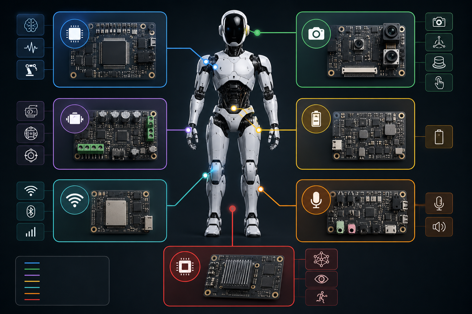
The entire robot is actually a collaboration of dedicated PCBs:
| Subsystem | Function | Key Components | Common Interfaces | | :--- | :--- | :--- | :--- | | Control System | Main board MCU/MPU handles real-time processing, decision-making, motion control | Ingest sensor data, run AI algorithms, send control signals to actuators | I2C, SPI, UART, GPIO, CAN, EtherCAT | | Sensor Interface | Dedicated sensor PCB connects camera, IMU, LiDAR, tactile sensors, microphones | Accurately collect data and send back to main board | I2C, SPI, MIPI CSI, UART, Ethernet | | Motor Drive | servo, BLDC, stepper motors controlled by dedicated motor driver PCBs | Ensure precise motion and limb coordination | PWM, GPIO, SPI, EtherCAT, RS485 | | Power Management | Convert battery voltage to required voltages, distribute stably, provide overcurrent protection | Balance power consumption among actuators, sensors, processors | I2C, SMBus | | Communication Module | Internal data exchange via CAN, UART, SPI; external connectivity via Wi-Fi, Bluetooth (even 5G, LoRa) | Internal/external communication | – | | Audio Processing | Robots with voice interaction use dedicated board for microphone input and speaker output | Voice recognition | I2S, analog audio, SPI, USB |
Note: More advanced robots add a dedicated AI accelerator for deep learning vision, NLP, and reinforcement learning for motion adaptation, offloading heavy compute from the main CPU.
Flex and rigid-flex PCBs are essentially the backbone of humanoid robots – packing advanced technology into compact, highly deformable designs. Here’s how boards are used in different parts:
| Part | Function | Key Components | PCB Type & Benefits | | :--- | :--- | :--- | :--- | | Head | Centralized information processing | Cameras for facial/object recognition, environmental sensors (IR, ultrasonic, LiDAR), AI processor for real-time decision | Flex PCB: lightweight, conformable, easy sensor integration, supports eye contact, expressions, human-robot interaction | | Torso | Structural stability and system coordination | Main processor, power distribution unit, communication modules (Wi-Fi/BT/5G), IMU | Multilayer flex PCB for high-density interconnect in limited space; rigid-flex combines robustness with flexibility | | Arms & Hands | Precise motion and dexterity | Joints and actuators, tactile/pressure sensors, micro motors for fingers | Flex PCB: provides movement flexibility, reduces weight, improves control response | | Legs & Feet | Locomotion and balance | High-torque motors, gyroscopes and accelerometers, force sensors for terrain adaptation | Rigid-flex PCB: structural reinforcement while retaining flexibility, improves terrain adaptation and balance | | Multiple locations | Perception and environmental awareness | 360° vision cameras, LiDAR for 3D mapping, ultrasonic/infrared sensors for obstacle avoidance | Flex PCB: compact sensor integration, efficient data transmission |
Notably, good flex PCB manufacturers can produce boards rated for 200,000 bending cycles – critical for constantly moving joints.
AI is the robot’s brain, responsible for real-time data processing, decision-making, and task execution – all requiring high-performance circuits. Flex PCB contributes by providing high-density interconnects for fast, efficient data processing, supporting AI learning and adaptation, and optimizing space and flexibility in compact designs.
Materials like DuPont Pyralux TK and Panasonic FELIOS R-F775 are transforming robotics PCB manufacturing. Flexible substrates enable complex, agile movements; high-frequency materials aid miniaturization, achieving small size and high performance. They also offer advantages in thermal stability and harsh environment tolerance, suitable for prolonged operation in dangerous or extreme conditions.
Key manufacturing points:
A common additive manufacturing approach – printing highly conductive traces directly onto flexible substrates, eliminating traditional etching or laser direct imaging.
Advantages:
A caution: nano-silver ink printing works well for single- and double-sided boards, but not for multilayer boards – evaluate carefully before choosing this path.
HDI PCBs for robots must be ultra‑compact yet capable of complex interconnects. ELIC technology allows direct connection between multiple layers, reducing signal transmission delay and improving reliability.
Key advantages:
Additionally, pairing with low Dₖ, low Df materials (e.g., Isola I‑Tera, I‑Speed) ensures high-speed signals maintain integrity and low loss.
Embedding capacitors and resistors directly into PCB layers, or even integrating the AI processor into the board with SiP, dramatically saves space, reduces external volume, and improves signal integrity. SiP enables faster real-time decisions; embedding RF and power modules reduces signal loss and improves energy efficiency – very beneficial for long‑duration robot operation.
Robotics PCBs are complex, requiring stringent quality control. AI inspection can catch micro‑defects invisible to the naked eye:
Integrating IoT into PCBs allows robots to communicate effectively with various sensors and devices, collect real-time environmental data, and greatly enhance autonomous operation. For example, IoT‑enabled PCBs give robots stronger object recognition capabilities, reduce human intervention, and improve safety and efficiency, especially in hazardous environments.
Overall, IoT helps robots better interpret and respond to their surroundings, with higher precision and autonomy, expanding their range of applications.
Designing PCBs for humanoid robots is a detail‑intensive task – space, performance, durability, and environmental factors all matter. By using advanced materials and processes correctly, the resulting boards can seamlessly integrate into the system, making the robot not only more agile but also longer‑lasting.
For R&D engineers, the most valuable takeaway from this article is how to simultaneously satisfy the three constraints of “space‑limited × high‑speed × moving” – the choices of flex/rigid‑flex materials, HDI + ELIC, rolled annealed copper, etc., are applicable to wearables, automotive, and consumer products as well. The concepts of protocol selection (SPI for low latency, I2C for multi‑device) and “place PCBs as close as possible to sensors and motors” are design intuitions that any real‑time control system should internalize. After reading this, the checklist in your mind when evaluating your own product’s stack‑up and layout will be a bit more complete.