June 9, 2026
This guide delves into the physical mechanisms behind tolerance failures in PCB manufacturing, identifying the hidden culprits, and provides practical defense strategies for R&D and project management teams.
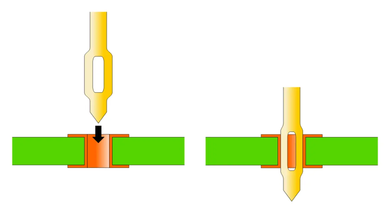
To solve press-fit challenges on the production line, one must first understand the operating principle of Press-fit technology.
Completely different from soldering methods that rely on heating to melt metal alloys, press-fit technology relies solely on pure "mechanical force" to achieve a reliable gas-tight connection.
When the metal terminal of a connector is pressed into the PCB's Plated Through Hole (PTH) with significant force, intense friction and compression occur between the terminal and the copper layer of the hole wall. During this process, the microscopic oxide layer on the contact surfaces is forcibly broken, exposing pure metal lattices, thereby forming a tight bond similar to cold welding. This connection effectively isolates air and moisture, ensuring absolute stability of the contact resistance.
To improve fault tolerance, the industry widely adopts Compliant Pins, the most classic design of which is the "Fish-eye" pin.
A common specification for fish-eye terminals in practice, such as pin headers with a 2.50 mm pitch, has a pin size of approximately 0.64 mm. The fish-eye pin features a hollow, elliptical elastic structure in its middle:
However, if the PCB hole diameter is too small, the immense mechanical stress will cause the PCB substrate to tear and delaminate; if the hole diameter is too large, insufficient positive contact pressure will lead to poor contact and intermittent signal issues.
The hole diameter tolerance for general DIP insertion holes is typically specified as ±0.075 mm. However, this standard is absolutely unacceptable for Press-fit holes.
The tolerance for standard press-fit holes must be strictly controlled within ±0.05 mm; some high-speed signal connectors even demand an extremely stringent ±0.025 mm.
In actual PCB production, the biggest invisible killers affecting hole diameter control include the following three points:
1. Drill Wear The FR-4 substrate of PCBs contains high-hardness glass fiber. When CNC drilling machines operate continuously at tens of thousands of RPM, the cutting edges of the drill bits constantly wear down and become dull, causing the drilled hole diameters to gradually shrink. There can be a significant size difference between the first hole and the thousandth hole on the same panel.
2. CAM Drill Size Compensation The design engineer specifies the "finished hole diameter," but the PCB manufacturer must预先放大 the hole diameter to预留 space for the subsequent pattern plating hole copper (typically 20 μm to 25 μm thickness). If the current distribution in the plating bath is uneven, excessive hole copper thickness will directly consume the valuable tolerance margin.
3. Surface Finish Process Surface finish is the final watershed determining the success or failure of tolerance control. The following table shows the impact of common industry processes on press-fit holes:
| Surface Finish Process | Hole Diameter Uniformity | Tolerance Control Capability | Suitability for Press-Fit Holes | Potential Process Risks | | :--- | :--- | :--- | :--- | :--- | | HASL | Poor (teardrop-shaped) | Poor | Highly Not Recommended | Uneven solder thickness can prevent insertion; forced pressing may scrape off solder whiskers causing micro-shorts | | ENIG | Excellent (uniform deposition) | Excellent | Strongly Recommended | Provides excellent surface flatness and dimensional accuracy, long oxidation resistance life | | OSP | Good (very thin thickness) | Good | Conditionally Applicable | Requires preventing oxidation issues after high-temperature reflow, limited storage time |
Hot Air Solder Leveling (HASL) is fatal for press-fit holes; residual solder droplets completely破坏 the cylindricity of the hole. In comparison, the Immersion Gold (ENIG) process deposits uniformly on the copper surface and is the best means of defending against tolerance loss.
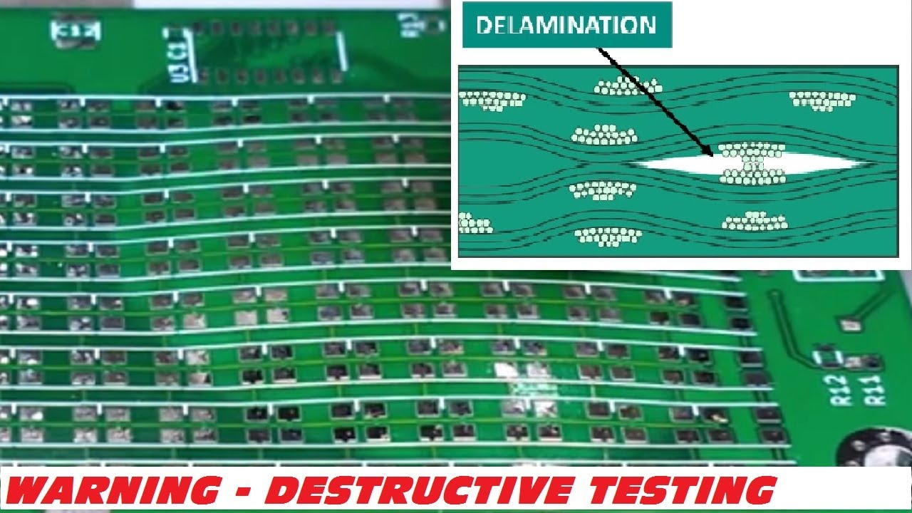
When the production line reports that a connector is pressed in with a crisp cracking sound, it usually indicates severe PCB Delamination has occurred.
The root cause of delamination lies in the substrate's inability to withstand the immense Z-axis stress generated when the fish-eye pin expands the hole wall. Using laminates with a low Tg (Glass Transition Temperature), or insufficient lamination curing, will significantly increase the probability of delamination.
 DFM Quick Checklist for Press-fit PCB
Before engineers send the design to the board house for fabrication, be sure to check the following list:
When press-fit failures occur during the trial production phase, mastering the correct troubleshooting logic can effectively break down departmental barriers:
1. Preventing Mechanical Interference When implementing精密 connectors, choose models with pins featuring polarity design (foolproof定位) to prevent reverse blind insertion on the production line. Furthermore, the mating height must be greater than the soldering height of surrounding SMD components; otherwise, the press-fit tooling can easily crush nearby capacitors or resistors.
2. Pin Length for Mixed Processes If using hybrid connectors that are partially press-fit and partially hand-soldered, the length of the soldered pins protruding from the PCB must be greater than 0.5 mm.
3. Rapid Failure Analysis (FA) for Poor Contact When Automated Test Equipment (ATE) shows an open circuit or no signal, it is often due to terminal rust, environmental contamination, or ink污染 the hole wall, causing reduced contact pressure of the fish-eye pin. Rapid Verification Method: Remove the connector and reinsert it. The re-friction process can scrape off surface contaminants. If the contact resistance returns to normal, the cause can be judged as microscopic contamination inside the hole or excessive tolerance.
Press-fit assembly, while seemingly a simple operation, is actually a comprehensive工艺 spanning materials science, CNC machining, and surface chemistry. Simply blaming the PCB manufacturer for "inaccurate drilling" or the mechanical supplier for "terminals being too large" does not help solve the underlying problem.
Only by strictly adhering to DFM specifications at the design source, resolutely using ENIG to lock in hole diameter accuracy, and requiring the board house to implement strict drill bit life management, can the breeding ground for tolerance loss be effectively eliminated.
After reading this defense guide, take a moment to reflect: during your company's NPI trial production phase, when faced with the惨状 of press-fit holes not accepting pins or board delamination, which department usually ends up taking the blame? Building cross-functional DFM consensus is the only solution to end this tolerance game.
Need Press-fit PCB DFM Support?
If your design includes Press-fit connectors, hole diameter tolerance and plating control will be critical to success.
eCloud provides PCB prototyping services with professional Engineering Review to help you prevent press-fit failures and delamination risks in advance during the NPI phase.
