August 16, 2026
Many engineers pour attention into copper weight, trace width, and impedance — yet miss that even when the air gap looks generous on the schematic, a permanent conductive carbon track can slowly burn between two high-voltage pads in a humid, dusty environment. This article walks from the definition and measurement of CTI through to how it directly governs creepage distance, material choice, and safety certification.
CTI (Comparative Tracking Index) is the maximum voltage (in volts) that an insulating material surface can withstand without forming a conductive carbonised path under wet, contaminated conditions. It measures a laminate surface's resistance to tracking once dirt and moisture are involved.
 Measurement follows the IEC 60112 standard: two platinum electrodes apply voltage across the material surface while an ammonium chloride conductive solution is dripped between them at fixed intervals. The voltage that survives 50 drops without a tracking failure becomes the CTI rating. A few key points:
A high‑voltage gap can fail in two very different ways, and engineers often guard against only one. The first is the clean air arc, controlled by clearance. The second is far sneakier: surface tracking — contamination slowly degrades the insulator surface until a permanent carbonised conductive path forms.
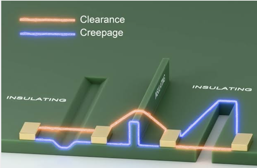 It doesn't need a large air gap to jump; it "creeps" along, fed by humidity, dust, flux residue, and the electric field. Once the carbon path forms, it is permanent and conductive — effectively turning your insulator into a conductor. CTI exists precisely to prevent this second failure mode.
CTI matters because it is written directly into the "creepage distance" in safety tables. Creepage is the shortest distance between two conductors along the insulating surface; clearance is the shortest distance through air. Tracking occurs along the surface, so CTI controls creepage. The relationship is clear: the higher the CTI, the shorter the creepage required for a given working voltage and pollution degree; the lower the CTI, the farther conductors must be spaced.
Standards such as IEC 62368‑1 and IEC 60664‑1 quantify this through material groups:
Pollution degree is equally important: Pollution Degree 2 (typical indoor, office environments) and Pollution Degree 3 (industrial, conductive dust, condensation) demand very different creepage. The safety table is indexed by working voltage × pollution degree × material group — improve the material group, and you can legitimately close the gap.
The bad news: most common FR‑4 grades sit around 175 V CTI, in Material Group IIIa. That's fine for many low‑voltage applications, but at high voltage it forces the largest creepage in the table. When you need better, fabricators can supply high‑CTI laminates engineered for tracking resistance — using modified resin systems and fillers to reach CTI ≥ 600 V (Material Group I).
| Material | Typical CTI (V) | Material Group | Best Fit | | :--- | :--- | :--- | :--- | | Standard FR‑4 | ~175 | IIIa | Low‑voltage digital, general use | | Mid‑grade FR‑4 | 200–400 | IIIa / II | Moderate voltage, controlled environment | | High‑CTI FR‑4 | 400–599 | II | Mains power, compact spacing | | Premium high‑CTI FR‑4 | ≥600 | I | High‑voltage, Pollution Degree 3, certified products | | Ceramic / specialty | ≥600 | I | Extreme HV and harsh environments |
Standard FR‑4 is cheap and available everywhere, but it eats space at high voltage; stepping up to Group II or Group I meaningfully shortens the required creepage — often worth it in a dense design.
No single CTI value is "correct." Choose wrong and you either waste cost or invite a tracking failure or certification rejection. Rules of thumb for matching material to mission:
Choosing the right laminate is only the start; high‑voltage layout details are what cash in the material's CTI. Techniques that raise real‑world tracking resistance:
Also keep flux residue and ionic contamination off high‑voltage areas — because that contamination is exactly what the CTI test simulates. The cleaner the surface, the closer your chosen material group performs to its rating.
A CTI number on the datasheet is one thing; preserving the surface quality that delivers it is a matter of process discipline. High‑CTI laminate ships with a guaranteed CTI, but improper processing can undermine the surface — and since tracking resistance lives only on the board surface, this is where a disciplined fab has to step in. In high‑voltage fabrication, eCloud pays particular attention to a few key controls:
CTI is the silent guardian of high‑voltage board safety — it determines whether your laminate resists surface tracking, dictates the creepage you must observe, and ultimately decides whether the board earns its safety mark. The easiest way to fail a certification you thought was in the bag is to treat CTI as an afterthought. The right approach is to work backward: define working voltage and pollution degree first, then pick the material group that clears the creepage table with margin.
As power densities keep climbing across EVs, solar, and industrial high‑voltage systems, getting CTI right only grows more important. eCloud offers a range of certified high‑CTI laminates and can run DFM review on creepage, clearance, and mask coverage early in the design — surfacing high‑voltage spacing problems before a material change gets expensive. For your next high‑voltage power or charging project, reach out to our engineering team while material and layout are still on the table.
