1. Introduction: The PCB Material Revolution in the Data Deluge
In the field of electronic hardware R&D in 2025, the slowdown of Moore's Law contrasts sharply with the exponential growth of data transmission rates. With the explosive growth of training demands for Artificial Intelligence (AI) Large Language Models and the continuous deployment of 5G/6G communication infrastructure, system bottlenecks are rapidly shifting from internal chip computing power to the interconnection channels between chips (Chip-to-Chip) and between boards (Board-to-Board).
For R&D engineers, PCB Layout engineers, and electromechanical students in Taiwan, the Printed Circuit Board (PCB) is no longer merely a mechanical support for electronic components; it has evolved into a complex active component and a crucial link in the high-speed signal transmission Channel. As signal rates leap from early 10 Gbps NRZ to 56 Gbps PAM4, and even to the cutting-edge 112 Gbps and 224 Gbps SerDes technologies, the physical properties of PCB dielectric materials—Dielectric Constant (Dk) and Dissipation Factor (Df)—have become key variables determining system success or failure.
This report aims to provide a detailed research report on high-frequency high-speed PCB materials for professional readers. We will delve into the material physics mechanisms behind Signal Integrity (SI), analyze the technical moats of the three international giants (Rogers, Panasonic, Isola), and focus on deconstructing how Taiwan's local CCL (Copper Clad Laminate) trio—Elite Material (EMC), ITEQ, and Taiwan Union Technology (TUC)—have emerged in the global AI server supply chain. Furthermore, this report will provide practical material selection strategies based on "Cost-Performance Ratio" (CP value) and "Supply Chain Resilience" to assist engineers in achieving the optimal balance between extreme performance and cost control.
2. Physical Basis of High-Frequency High-Speed Materials and Signal Integrity Mechanisms
To precisely select PCB materials, one must return to the physical essence of electromagnetic field theory. "High Frequency" and "High Speed" are essentially the same at the physical level: they both concern the propagation behavior of electromagnetic waves in Transmission Line structures.
2.1 Dielectric Constant (Dk) and Signal Propagation Velocity
Dielectric Constant (Symbol: Dk) is a physical quantity measuring the ability of an insulating material to store electrical energy. In PCB transmission line design, the value of Dk directly determines the propagation speed of electromagnetic waves in the medium. According to Maxwell's Equations, the signal propagation speed Vp can be expressed as:
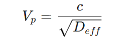
Where c is the speed of light in a vacuum (approximately 3 × 10^8 m/s), and Deff is the effective dielectric constant.
It can be seen that the lower the material's Dk, the faster the signal transmission speed, and the smaller the Propagation Delay.
2.1.1 Engineering Significance of Low Dk
For High-Speed Digital (HSD) circuits, low Dk materials bring three significant advantages:
- Shortened Timing Delay: In long-distance transmission (such as server backplanes), low Dk materials can significantly reduce the Time of Flight of signals from the transmitter (Tx) to the receiver (Rx). This is crucial for parallel buses with extremely strict Timing Margins like DDR5 or PCIe Gen 6.
- Reduced Capacitive Effect: Lower Dk means reduced conductor-to-ground capacitance, which helps improve signal Rise Time and reduces signal tailing.
- Trace Width Advantage and Impedance Control: Maintaining the same characteristic impedance (e.g., 50 Ω Single-ended or 100 Ω Differential), using low Dk materials allows designers to use wider trace widths. Wider traces not only reduce Conductor Loss but also reduce impedance variation caused by Etching Tolerance. For example, for FR-4 with Dk=4.2, a 50 Ω trace width might be 6 mil; whereas for Rogers RO3003 with Dk=3.0, the trace width for the same dielectric thickness could increase to 8-9 mil, which is a major advantage for manufacturing yield.
2.2 Dissipation Factor (Df) and Signal Attenuation
Dissipation Factor (Symbol: Df) defines the efficiency with which a material converts electrical energy into heat under an alternating electric field. It is the core indicator for measuring Dielectric Loss.
Total Insertion Loss consists mainly of two parts:
- Conductor Loss: Derived from the DC resistance of copper wires and the Skin Effect at high frequencies.
- Dielectric Loss: Derived from the polarization hysteresis of insulating material molecules.
The approximate formula is:

As seen from the formula, dielectric loss is proportional to frequency f. In the low-frequency band (< 1 GHz), conductor loss dominates; but in the high-frequency band (> 10 GHz), the proportion of dielectric loss rises rapidly, becoming the main killer of signal attenuation. Therefore, for 5G millimeter-wave (28 GHz, 39 GHz) or 112 Gbps PAM4 (fundamental frequency approx. 28 GHz) applications, choosing materials with extremely low Df is the only way to maintain the opening of the Signal Eye Diagram.
2.3 The Invisible Killer: Surface Roughness
In the traditional FR-4 era, to increase the Peel Strength between copper foil and resin, the copper surface was usually roughened to form microscopic peak-like structures. However, at high frequencies, when current flows concentrated within the Skin Depth on the conductor surface, rough surfaces lengthen the current path and generate parasitic inductance, causing a sharp increase in conductor loss.
2.4 Fiber Weave Effect and Signal Skew
PCB substrates are typically composites of resin and Glass Fabric. The Dk of glass fiber (approx. 6.0) is much higher than that of resin (approx. 2.5-3.0). Traditional glass cloth weaves are relatively loose (e.g., 1080, 7628 models), leading to uneven local Dk distribution on the board.
When two wires of a Differential Pair run over a glass bundle (High Dk) and a resin gap (Low Dk) respectively, their propagation speeds will differ, causing a phase difference at the receiver, known as Glass Weave Skew. This severely destroys the Common Mode Rejection Ratio, increases Electromagnetic Interference (EMI), and causes the differential signal eye diagram to close.
Solutions:
- Spread Glass / Flat Glass: Models like 1067, 1086, 3313, 1078, etc., flatten the glass yarn bundles to reduce gaps, making Dk distribution more uniform.
- Zigzag Routing: Designing traces at a 10-15 degree angle to the glass fiber warp/weft direction to average out the Dk influence, though this wastes routing space.
3. High-Frequency High-Speed Material Classification and Selection Standards
Although IPC-4101 and IPC-4103 provide basic specifications, the industry practically classifies materials based on "Loss Bucket" (Transmission Loss Level). This is the common language for communication between RD and PCB factories.
3.1 Industry Common Loss Classification (@ 10 GHz)
We categorize materials into five levels based on their Df value at 10 GHz:
| Classification | Typical Df Value | Typical Application Scenarios | Technical Features | Representative Materials |
| :--- | :--- | :--- | :--- | :--- |
| Standard Loss | 0.015 ~ 0.025 | Consumer electronics, Low-speed logic, < 1 GHz | FR-4 Epoxy Resin | Isola 370HR, Nanya NP-140 |
| Mid Loss | 0.010 ~ 0.015 | Entry-level servers, Automotive entertainment, < 6 GHz | Modified Epoxy + PPO | Megtron 4, TU-747, IT-150G |
| Low Loss | 0.005 ~ 0.010 | 10G/25G Ethernet, High-end PC motherboards | PPO/PPE Resin System | Megtron 6 (Early), IT-170GRA |
| Very Low Loss | 0.002 ~ 0.005 | 56G PAM4, 5G Antennas, High-end Servers | High content PPO/PPE + Low Dk Glass | Megtron 6/7, IT-968, EM-890K |
| Ultra/Extreme Low Loss | < 0.002 | 112G/224G, 77GHz Radar, AI Accelerator Cards | Special Resin / PTFE / Ceramic Filled | Megtron 8, EM-892K, RO3003, Tachyon 100G |
3.2 Key Selection Parameter Checklist
When selecting materials, RDs should evaluate the following parameters:
- Dk / Df Stability with Frequency: Premium materials should have a Dk variation of less than 5% across the 1 GHz to 50 GHz range.
- Dk / Df Stability with Temperature (TCDk): For outdoor 5G base stations or high-heat AI servers, materials must maintain stable characteristics over a wide temperature range. The Rogers RO3000 series performs best in this regard.
- Moisture Absorption: The Dk of water molecules is as high as 70+, so even trace amounts of moisture absorption can cause material Dk/Df to skyrocket. High-end PPO/PTFE materials typically have moisture absorption < 0.1%.
- Thermal Reliability (Tg & Td): Lead-free processes require material Td (Decomposition Temperature) > 340°C and Tg (Glass Transition Temperature) > 180°C to withstand multiple Reflow cycles without delamination.
- Anti-CAF Performance: The ability to prevent Conductive Anodic Filament growth which causes short circuits under high voltage and high-density routing.
4. Deep Dive into International Giants: Rogers, Panasonic, Isola
In the PCB material world, these three brands represent the highest standards in different fields.
4.1 Rogers Corporation: The Absolute Ruler of RF & Microwave
The name Rogers is almost synonymous with "High-Frequency Microwave Boards." Its product line is primarily based on PTFE (Polytetrafluoroethylene) and ceramic-filled hydrocarbon technologies, focusing on solving the most rigorous RF challenges.
4.1.1 RO4000 Series: Revolutionary Material Breaking Processing Barriers
- Tech Core: RO4000 (e.g., RO4350B, RO4003C) is not traditional PTFE, but Ceramic-filled Hydrocarbon reinforced with glass fiber.
- Killer Advantage: It possesses electrical performance close to PTFE (stable Dk, extremely low Df) but is fully compatible with standard FR-4 processing. PCB factories do not need to buy expensive plasma etching equipment or high-temperature presses. This makes it the top choice for 4G/5G Power Amplifiers (PA), small cells, and automotive radar, striking a perfect balance between performance and mass production cost.
- Hybrid Application: Due to RO4000's CTE (Coefficient of Thermal Expansion) matching well with copper and FR-4, it is frequently used in Hybrid Stackup designs with FR-4 (e.g., outer layers use RO4350B for RF signals, inner layers use cheap FR-4 for digital control), drastically reducing multilayer board costs.
4.1.2 RO3000 Series: The Pursuit of Extreme Performance
- Tech Core: Ceramic-filled PTFE composite.
- Features: Offers extremely low Df (approx. 0.001 @ 10 GHz) and excellent Dk temperature stability (TCDk almost 0).
- Application: 77 GHz automotive millimeter-wave radar, GPS antennas, military radar. This is the uncompromising choice for performance, but processing difficulty is higher.
4.2 Panasonic: The Synonym for High-Speed Digital Circuits (Megtron Series)
If Rogers is the King of RF, Panasonic's Megtron series is the "Gold Standard" in the High-Speed Digital domain.
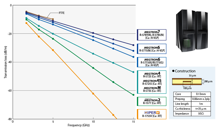
4.2.1 Megtron 6 (M6): Defining Industry Standards
- Status: Long the benchmark for the Very Low Loss level. When engineers say "I want M6 grade material," they typically mean Df approx. 0.002-0.004, excellent heat resistance, and suitable for high layer count lamination.
- Tech: Uses a high-heat Polyphenylene Ether (PPE) resin system.
4.2.2 Megtron 7 (M7) & Megtron 8 (M8): Evolution for the AI Era
- Megtron 7 (M7): Developed for 400G network equipment, further reducing Df. Mainstream for high-end switches.
- Megtron 8 (M8): Designed for 800GbE and AI servers, possessing the lowest transmission loss in its class (approx. 30% lower than M7). It uses ultra-low roughness copper foil and specially treated low-loss glass cloth.
- Megtron 9 (M9): Targeted for the 224 Gbps generation.
4.3 Isola Group: Solid Force in Western Markets
Isola is a US-based major material manufacturer. While its volume in Asia is squeezed by Taiwanese and Japanese competitors, it has a deep foundation in North American and European aerospace, defense, and industrial control sectors.
- I-Tera MT40: Isola's main product competing with M6. Dk approx. 3.45, Df approx. 0.0031. Advantage lies in excellent thermal stability (Tg 200°C).
- Tachyon 100G: Designed for rates above 100 Gbps, directly competing in the M7 market.
5. The Light of Taiwan: Rise of the Local Supply Chain (EMC, ITEQ, TUC)
Taiwan possesses the world's most complete PCB industry cluster. Recently, the local CCL trio—EMC, ITEQ, TUC—have successfully caught up with or surpassed international giants in technology, becoming core forces in the Nvidia, AMD, and Intel AI server supply chains.
5.1 Elite Material Co. (EMC): The Biggest Winner in AI Servers
EMC is currently the global leader in Halogen-free high-end laminates. In Nvidia's AI server architecture (e.g., H100, GB200), EMC materials occupy a very high share, especially on the critical OAM (Open Accelerator Module) and UBB (Universal Baseboard).
5.1.1 Flagship Products:
- EM-890K / EM-891K: Benchmarked against Megtron 7 (Ultra Low Loss). Halogen-free, High Tg (>200°C), excellent anti-CAF. Optimized for HDI and multiple lamination.
- EM-892K / EM-892K2: Benchmarked against Megtron 8 (Extreme Low Loss) for 112 Gbps/224 Gbps. Df reduced to 0.0017 (at 10 GHz) or lower. Heavily adopted in Nvidia Blackwell architecture.
5.2 ITEQ Corporation: The Comprehensive Challenger
ITEQ has deep roots in networking, servers, and automotive electronics.
5.2.1 Flagship Products:
- IT-968 / IT-968SE: Currently the most common alternative for M6/M7 grades in the server market with high cost-performance. The SE (Special Edition) version pairs HVLP copper foil with low Dk glass cloth, with loss performance rivaling M7. High penetration in Intel Eagle Stream and AMD EPYC platforms.
5.3 Taiwan Union Technology (TUC): Persistence in High Reliability
Known for its "ThunderClad" series, TUC has loyal customers in high-end switches, core routers, and aerospace industrial controls requiring extreme reliability.
5.3.1 Flagship Products:
- ThunderClad 3 (TU-933+): Very Low Loss, excellent thermal robustness, suitable for 30+ layer ultra-thick backplanes.
- ThunderClad 4 (TU-943): Extreme Low Loss, challenging the M8 market.
6. Deep Analysis: Material Strategy for AI Servers and 5G Applications
6.1 Nvidia AI Server (GB200/H100) Material Breakdown
A typical AI server rack contains various PCBs with distinct material requirements:
6.1.1 OAM (Open Accelerator Module) / GPU Card
- Function: Carries GPU chips and HBM memory for core computing.
- Requirements: Extreme Signal Integrity (112G/224G SerDes), High Layer Count (20-30 layer HDI), excellent heat dissipation.
- Material Selection: Must use Extreme Low Loss (M8 Grade).
- Suppliers: EMC (EM-892K2), Panasonic (Megtron 8), Doosan.
- Key Tech: Must use HVLP Copper Foil and Low Dk Spread Glass.
6.1.2 UBB (Universal Baseboard) / GPU Motherboard
- Function: Carries 8 OAM modules, providing interconnection (NVLink) and power distribution.
- Requirements: Large Size (Big Board), High Layer Count (24-30 layers), Long distance transmission.
- Material Selection: Typically Ultra Low Loss (M7 Grade).
- Suppliers: EMC (EM-890K), ITEQ (IT-968SE), Panasonic (Megtron 7).
6.1.3 CPU Mainboard and Switch Board
- Function: Carries CPU, DRAM, and external network switch chips.
- Requirements: PCIe Gen 5/6 support.
- Material Selection: Very Low Loss (M6 Grade) or Low Loss (M4 Grade) is sufficient.
- Suppliers: ITEQ (IT-170GRA/IT-968), Isola (370HR/I-Tera), TUC (TU-883).
6.2 5G Base Stations and Millimeter Wave Radar
- AAU Antenna Board: Requires extremely low dielectric loss and PIM. Rogers RO4730G3 or RO3003 are mainstream.
- 77GHz Automotive Radar: Almost monopolized by Rogers RO3003 due to irreplaceable Dk stability in mmWave bands.
7. Practical Selection Guide for Taiwan RDs: CP Value and Supply Chain Thinking
7.1 Cost-Performance (CP Value) Analysis Matrix
| Price Tier | Price Multiplier (vs FR-4) | Representative Brands | Suggested Application Strategy |
| :--- | :--- | :--- | :--- |
| Tier 1 (Premium) | 10x - 20x | Rogers RO3000, Taconic (Pure PTFE) | Only for 77GHz Radar, Aerospace, Core RF Filters. Irreplaceable performance, extremely high cost. |
| Tier 2 (High) | 3x - 5x | Rogers RO4000, Megtron 8, Tachyon 100G | Used for 5G PA, 112G AI Accelerator Cards. RO4000 is expensive but cheap to process; M8 is the performance peak. |
| Tier 3 (Mid-High) | 1.5x - 3x | Megtron 6/7, EM-890K, IT-968 | Main battlefield for Taiwan RDs. Standard for servers, switches, high-end PCs. Taiwan makers (EMC/ITEQ) offer extremely high CP value here. |
| Tier 4 (Standard) | 1x (Baseline) | Isola 370HR, IT-180A, Nanya NP-175 | General consumer electronics, industrial control mainboards. |
Expert Advice:
- Utilize Second Source: If the client specifies Megtron 6, boldly validate EMC EM-890K or ITEQ IT-968 for production in Taiwan. They usually offer equivalent performance but with 10%-20% lower cost and lead times reduced from 8-12 weeks (Japan) to 2-4 weeks (Taiwan).
- Hybrid Stackup: To reduce total cost, use "Outer layer Rogers + Inner layer FR-4". Note: CTE matching is critical to avoid warpage.
7.2 Procurement and Supply Chain Risk Alerts
- Glass Cloth & Copper Foil Shortage: AI server demand has strained supplies of Low Dk Glass Cloth and HVLP Copper Foil. RDs must confirm "Long Lead Time" risks before freezing designs.
- "M-Grade" Terminology Trap: "Use M6" usually means "M6 grade performance," not necessarily Panasonic M6. RDs should specify "Panasonic Megtron 6 or equivalent (e.g., EMC EM-890K)" on drawings to maintain procurement flexibility.
8. Conclusion and Future Outlook
The selection of High-Frequency High-Speed PCB materials is a comprehensive art blending physics, chemistry, material science, and supply chain management.
- For Extreme RF/mmWave applications, Rogers remains the unshakeable ruler.
- For AI Servers and High-Speed Digital, Panasonic Megtron defined history, but Taiwan's EMC and ITEQ have become dominant forces through technical breakthroughs and supply chain advantages.
- For engineers in Taiwan, mastering these micro-properties, understanding the roles of HVLP copper and Spread Glass, and leveraging the local supply chain are key competitive advantages in the AI computing era.
The material revolution for the 224 Gbps era, involving ultra-low loss resins and Glass Core substrates, is just beginning.
