Advancing Material Systems and PCB Fabrication Together
Explore M10 PCB material development, from low-loss resin and glass fabric to copper foil, fabrication readiness, and engineering validation.
As AI servers and networking equipment increase data transmission capacity, PCB materials are becoming an important part of high-speed interconnect design. When channels require more signal margin, material selection directly influences routing, stackups, and fabrication choices.
M10 materials have emerged as a development direction worth watching. The engineering challenge encompasses lower-loss material combinations and the ability to process, validate, and introduce them into actual products.
For R&D engineers and project managers, understanding M10 means identifying the conditions behind the material upgrade and determining whether the design and supply chain are ready.
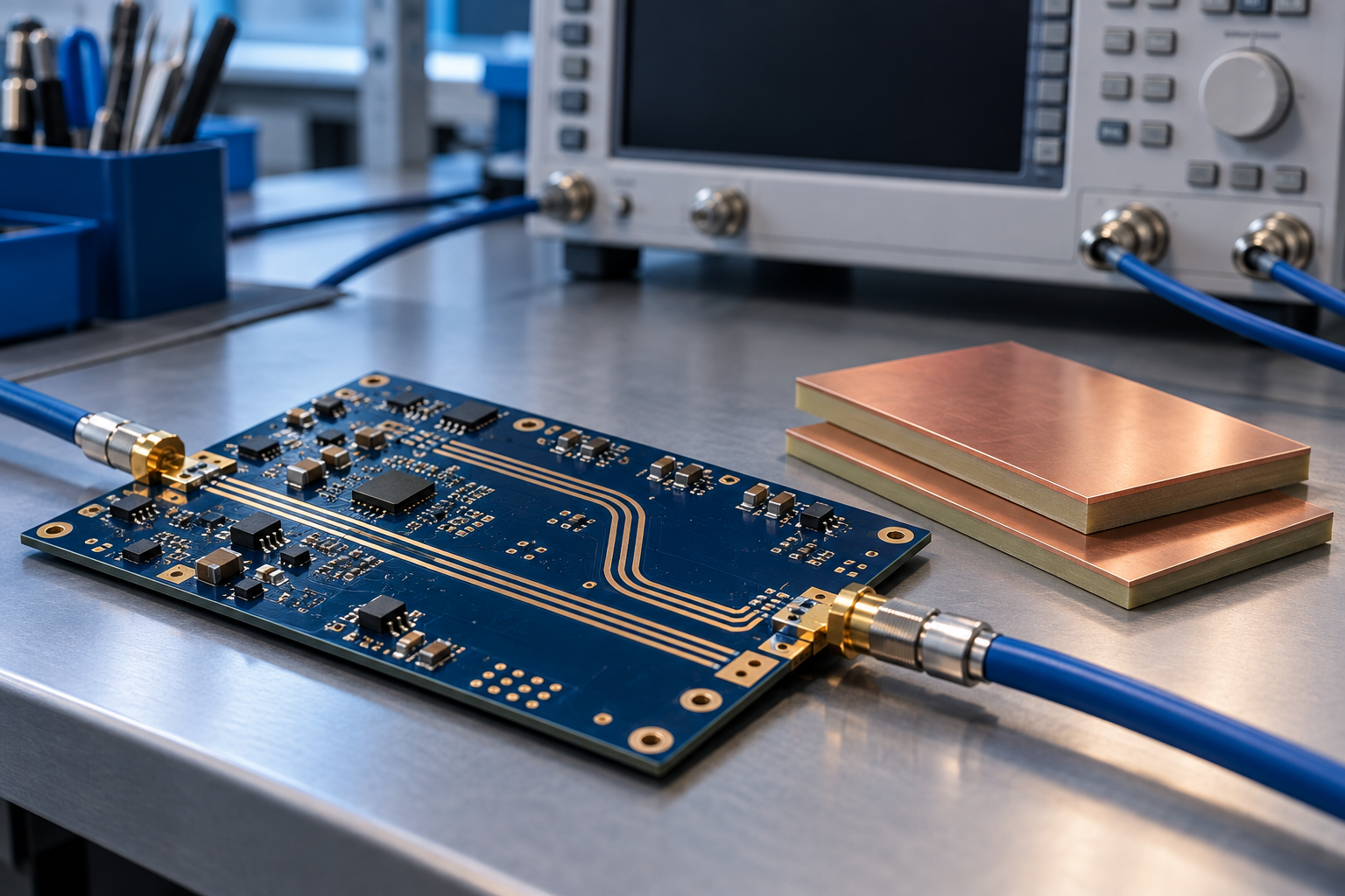 Developments in 800G and 1.6T networking equipment and high-speed interconnects such as 224G SerDes are driving interest in lower-loss materials that can support more demanding channels.
Industry reporting describes M10 as a direction still undergoing development and customer validation. Adoption discussions therefore need to address specific products: the material part number, construction, available test data, and the supplier's development and supply status.
The M10 label alone does not establish specific electrical properties, processing capabilities, or production availability.
An actionable engineering specification still requires complete part numbers, core and prepreg combinations, glass and copper foil configurations, and electrical data under applicable conditions.
Reference: TPCA coverage of high-speed, low-loss material upgrades
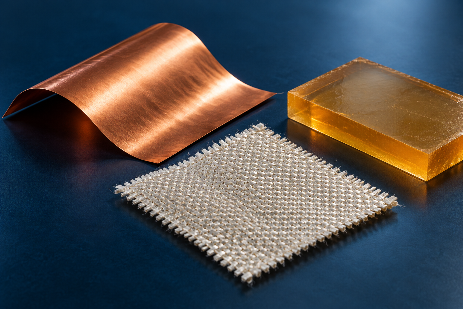 High-speed material performance depends on the complete combination. M10 discussions should address resin, glass fabric, and copper foil together.
The resin system influences dielectric loss while also needing to satisfy lamination, resin fill, and thermal requirements. Review electrical data alongside processing guidance rather than judging suitability from a lower dissipation factor (Df) alone.
When comparing candidate materials, align the test frequency, method, and specimen construction to make the comparison meaningful.
Glass fabric contributes to the material's electrical behavior. Differences between the dielectric properties of glass and resin can introduce propagation delay mismatch, or skew, in differential pairs.
An M10 review should therefore consider glass type, weave construction, and routing conditions alongside overall dielectric constant (Dk). Low Dk, low Df, and low thermal expansion are distinct properties that should be evaluated against the project's requirements.
Copper roughness affects insertion loss and phase response. As dielectric loss is reduced, the foil configuration also needs to be checked against the design model.
Terms such as VLP and HVLP provide a starting point for discussion. Actual selection should be based on the manufacturer's foil options, roughness data, and applicable conditions.
References: Panasonic material construction and electrical data, Isola fiber-weave analysis, and Rogers guidance on copper foil and fabrication effects
A project considering a supplier's M10-designated material should begin with the intended production construction.
Even if its electrical properties meet the target, confirm whether available core thicknesses, prepreg constructions, resin contents, and copper foil combinations can achieve the required dielectric thicknesses.
If prepreg combinations change to accommodate supply, reassess pressed thickness, resin fill, and impedance design. Reusing the original trace widths and spacing after a material change also requires renewed calculation and review.
For fabrication, use the candidate material's processing guidance to establish suitable lamination, drilling, and reliability validation approaches. Existing processing conditions should not be assumed to transfer unchanged.
This is a key adoption challenge for M10: material data, design models, and the actual production construction need to correspond.
Reference: Isola low-loss material product and processing documentation
When M10 enters a project discussion, establish the following checklist:
If the candidate material remains under validation, include material approval and trial fabrication in the project schedule. This gives design, procurement, and fabrication teams a consistent basis for adoption.
Interest in M10 reflects the movement toward lower loss, closer coordination of material constituents, and more demanding validation in high-speed PCBs.
For R&D engineers and project managers, adoption begins with a complete specification: confirm the material combination, establish the corresponding stackup, and use appropriate analysis and testing to assess project suitability.
If your project involves M10 or other high-speed, low-loss materials, share your Gerber files, target stackup, impedance requirements, and material specifications with eCloud to discuss fabrication conditions and outstanding questions before trial builds and production.
