Check the Complete Signal and Return Path
Review stackup, layer transitions, and fabrication details to support high-speed PCB design decisions.
A PCB has been fabricated to its specified impedance, yet the system still experiences intermittent disconnections, data errors, or waveform ringing. Repeatedly adjusting trace width can overlook other conditions affecting the signal.
Signal integrity (SI) concerns whether a signal can still be interpreted correctly when it reaches the receiver. Controlled impedance is one part of that assessment. Return paths, layer transitions, timing, loss, and power quality also require attention.
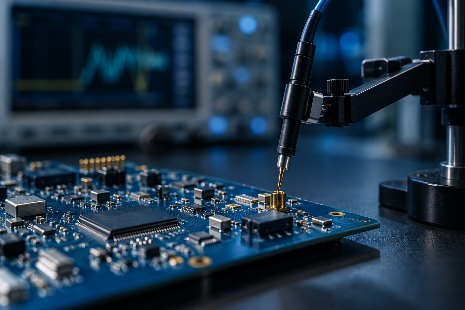 Clock frequency alone does not determine whether a trace requires transmission-line treatment. Signal rise and fall times, together with propagation time along the route, also matter.
Fast edges can make reflections from impedance changes significant. A relatively low operating clock frequency does not automatically eliminate high-speed routing concerns.
Start by checking device output edges, interface requirements, and the planned route. Then determine impedance, termination, and simulation needs rather than applying a single trace-length threshold.
Reference: High-speed signals and transmission-line matching
 Trace impedance depends on width, copper thickness, dielectric thickness, dielectric properties, and reference planes. It should be specified together with the stackup.
Before fabrication, collect the following in one confirmation document:
During engineering review, distinguish design trace width, production compensation width, and expected finished trace width. Clearly identify widths that cannot change so material and dielectric-thickness evaluations share the same assumptions.
Define separate acceptance criteria for bare-board impedance and system communication performance. Meeting the former still leaves connectors, components, and the complete route to be verified.
High-speed return paths are closely associated with reference planes. When a trace crosses a plane split or slot, return current may be forced to detour, increasing loop area and electromagnetic interference risk.
Review each route segment by asking:
When a signal changes between two ground reference layers, evaluate ground stitching vias near the signal via. A transition involving a different power reference plane requires a separate assessment of return-current transfer rather than automatically applying the same solution.
Reference: High-speed PCB return paths and plane arrangements
The unused portion of a signal via is called a via stub. It can resonate and affect channel performance. Branches added for test access can also introduce discontinuities.
Determine whether back-drilling is necessary from interface requirements, frequency range, stub length, and channel analysis. Where required, define the drilling side, target layer, and permitted residual stub in the fabrication data, and confirm manufacturing feasibility.
Balance test accessibility against electrical impact, avoiding unnecessary long branches added solely for convenient probing.
Reference: High-speed interface via and back-drilling guidelines
Equal physical lengths do not necessarily produce equal propagation delays. Different transmission-line structures and dielectric environments can introduce different delays. Review interface timing requirements rather than relying solely on length-matching results.
Assess crosstalk using trace spacing, parallel routing length, and distance to the reference plane. A simple spacing multiplier can support an initial review, but it cannot replace analysis of the actual stackup.
Longer high-speed channels also require conductor and dielectric loss assessment. Select materials against operating frequency, route length, and the channel budget rather than relying on a “low-loss” designation alone.
References: Transmission-line structures and delay differences, High-speed PCB channel design
Noise in the power distribution network (PDN) can reduce signal margins. Even a correctly valued decoupling capacitor can be affected by parasitic inductance if its connection loop is too long.
Review device power pins, capacitor pads, vias, and ground connections together instead of checking only whether the capacitor sits beside the device.
Record test conditions, including operating mode, load, temperature, and probing method, so measurements from different revisions can be compared.
Reference: Decoupling capacitor placement and loop inductance
Improving PCB signal integrity requires reviewing the transmitter, routing, reference planes, transitions, and receiver as one complete path, then translating design requirements into fabrication data.
For high-speed PCB prototyping, provide eCloud with Gerber files, the stackup, impedance requirements, and special process requirements to support confirmation of design needs and manufacturing conditions. Channel simulation and interface compliance verification should be arranged by the development team according to system requirements.
