December 31, 2025
Understanding Your Substrate Limits Through Tg and CTE
In the electronics R&D and Manufacturing (EMS) landscape, "FR-4" is the most ubiquitous specification. However, many engineers mistakenly believe that FR-4 represents a specific "formula" or "material." In reality, according to NEMA (National Electrical Manufacturers Association) definitions, FR-4 is merely a "Grade" representing a Glass-Reinforced Epoxy Laminate that meets the UL94 V-0 flame retardancy standard.
This means that whether it is a substrate for a low-end remote control or a Low Loss material for a high-end server, as long as it meets the above definition, it can be called FR-4. However, their heat resistance, Coefficient of Thermal Expansion (CTE), and electrical properties differ radically. With the Lead-Free Process pushing Reflow peak temperatures to 245°C–260°C, traditional low-end FR-4 can no longer cope, leading to frequent Delamination and Barrel Cracks. This article delves into how to select the correct material from a materials science perspective to solve thermal reliability issues in engineering practice.
FR-4 is a Composite Material composed of Epoxy Resin and Glass Fabric. The physical disparity between these two components is the root cause of all PCB warpage and failure.
Glass fiber provides the skeleton of the PCB. In the X/Y planar direction, the rigid glass fiber "constrains" the thermal expansion of the resin, suppressing the X/Y axis CTE to around 14–17 ppm/°C. This matches the CTE of Copper Foil (~17 ppm/°C), ensuring circuit stability.
However, in the Z-axis (thickness direction), there is no continuous glass fiber running through. The resin is free to expand in the Z-axis. This results in the Z-axis CTE of FR-4 (typically 40–60 ppm/°C) being significantly higher than that of the X/Y axis. This massive "Anisotropy" is the primary cause of via failure.
The weave density of different glass cloths determines the Resin Content (RC%) of the laminate, which in turn affects CTE and Signal Integrity (SI).
Engineering Note: Be aware of the "Fiber Weave Effect." In high-speed signal design, if differential pairs run separately over a glass bundle (Dk ~6.0) and a resin gap (Dk ~3.0) on 106 cloth, it causes impedance discontinuity and Skew, degrading signal quality.
Early FR-4 used Dicy (Dicyandiamide) as a curing agent. Its polar groups easily absorb moisture, and its heat resistance is relatively poor (Td ~300°C).
To adapt to lead-free processes, modern high-performance FR-4 (such as High Tg materials) have mostly switched to Phenolic (PN) curing systems. Phenolic forms a denser cross-linking network, offering higher thermal decomposition temperatures (Td >330°C) and better moisture resistance. This is the standard configuration for mid-to-high-end products.

Tg is the most cited parameter in PCB datasheets, but also the most misunderstood.
Tg is not the melting point. It is the critical temperature at which a polymer material transitions from a rigid "Glassy State" to a soft "Rubbery State."
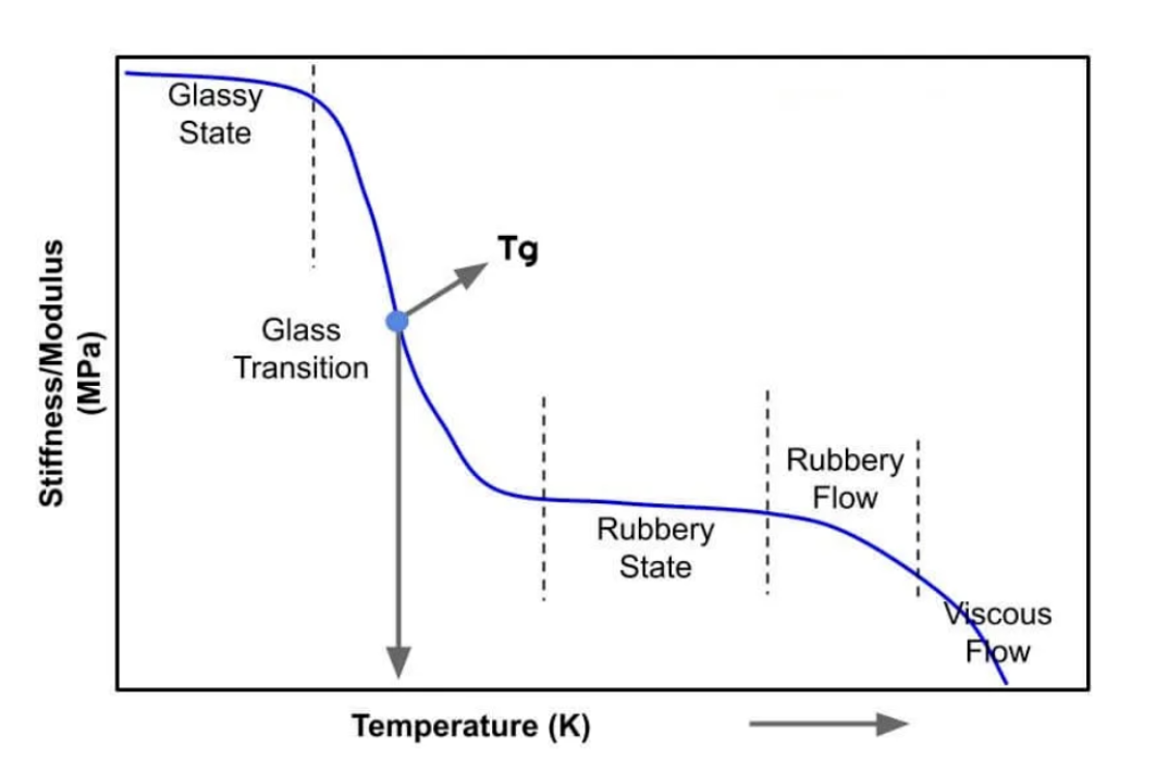
Microscopically, when the temperature exceeds Tg, molecular chains gain enough energy to move vigorously within the internal "Free Volume." At this point, the physical properties of the material undergo drastic changes:
Note on Testing Methods: When reading a Datasheet, look for Tg (DSC). Some manufacturers list the higher Tg (DMA) value to embellish specifications. Confusing the two can lead to errors in thermal budget assessment.
If Tg determines when the defensive line breaks, CTE determines the destructive force after the breach. In PCB failure analysis, Z-axis CTE is the most important indicator for assessing "Through-Hole Reliability."
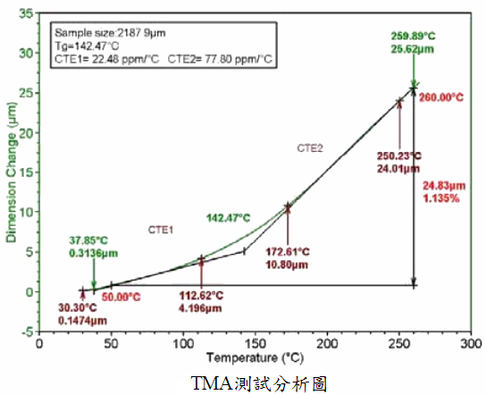
Reflow temperatures (245–260°C) are far higher than the board's Tg.
Looking at ɑ1 or ɑ2 alone is not intuitive enough. High-end boards (e.g., for servers) now prioritize the aggregate metric: Z-axis Expansion (50-260°C).
For thick boards with 12 layers or more, Low CTE materials (usually with Silica fillers) must be used; otherwise, the risk of barrel cracks is extremely high.
Many mistakenly believe that a higher Tg means better heat resistance. In fact, Td (Thermal Decomposition Temperature) is the absolute threshold determining if a board will suffer from "Delamination" or "Popcorn Effect."
Td is the temperature at which the material loses 5% of its weight. Lead-free processes require Td ≥ 340°C. If Td is too low, chemical bonds within the resin break during high-temperature reflow, generating gas (Outgassing). These gases are trapped inside the board, creating high pressure. Once the pressure exceeds the interlayer bond strength, delamination occurs.
Another culprit for delamination is Moisture. When a moisture-absorbed PCB hits high temperatures, water molecules instantly vaporize, expanding in volume by approximately 1600 times, generating massive vapor pressure.

Beyond peak temperature, we care about "how long it can last." T288 represents the time before delamination occurs at 288°C.
To give engineers a practical sense, we compare three common materials in the Taiwan market: Nan Ya NP-175, ITEQ IT-180A, and EMC EM-827.
| Parameter (IPC-TM-650) | Nan Ya NP-175 | ITEQ IT-180A | EMC EM-827 | Engineering Interpretation | | :--- | :--- | :--- | :--- | :--- | | Tg (DSC) | 175°C | 175°C | 175°C | All are High Tg materials. | | Td (TGA 5%) | 351°C | 350°C | 350°C | All meet lead-free requirements (Phenolic Cured). | | Z-CTE ɑ1 | 40-60 ppm/°C | 50 ppm/°C | 45 ppm/°C | Expansion before Tg; minor differences. | | Z-CTE ɑ2 | 270-300 ppm/°C | 250 ppm/°C | 225 ppm/°C | Key Differentiator: EM-827 performs best with minimal high-temp expansion. | | Z-Expansion (50-260°C) | ~3.5% | 3.0% | < 3.0% | Selection Core: For MLBs or HDI, <3.0% material is recommended (ITEQ/EMC). | | T288 (Time to Delam) | > 20 min | > 20 min | > 30 min | Higher values mean safer repair/rework. | | Filler | Yes | Yes | Yes (High Content) | Fillers lower CTE but wear drill bits; drilling parameters need adjustment. |
Selection Advice:
Board warpage is a nightmare for SMT lines, causing component tossing or Head-in-Pillow (HiP) defects on BGAs. Besides the material's thermal stress, Stackup Design is the primary culprit.
A PCB is like a sandwich; the top and bottom structures must be symmetrical.
Using traditional feeler gauges to measure warpage is insufficient for BGA packaging. The industry standard is Shadow Moiré equipment.
It uses optical grating interference to simulate the complete Reflow temperature profile (25°C -> 260°C -> 25°C), dynamically measuring PCB deformation at high temperatures. This detects hidden killers—boards that are "flat at room temperature but turn into potato chips inside the oven."
When material issues are suspected in a failure, the Standard Operating Procedure (SOP) is as follows:
In the electronics supply chain, balancing Cost Down and Reliability is an eternal challenge. Mastering the materials science of FR-4 prevents you from being misled by supplier jargon.
By utilizing scientific material selection and rigorous design, we can master the limits of these materials and manufacture high-reliability electronic products that represent quality.
