December 31, 2025
Why did my signal get lost?
It features a top-tier processor, the fastest memory, and the layout routing looks pristine. However, when the board comes back from prototyping and you power it up for measurement, you find the Eye Diagram is a collapsed mess, and the Bit Error Rate (BER) is frighteningly high.
At this moment, your manager might walk over, point at the green PCB, and ask: "Did you pick the wrong 'racetrack'?"
Exactly. In the world of high-speed circuits, the PCB is no longer just a plastic board holding components; it is a "racetrack." The surface material of this track—the PCB Laminate—directly determines how fast and how far your electronic signal (the "supercar") can travel.
This article won't bore you with complex Maxwell's equations. Instead, we will use plain language to guide R&D engineers through the two parameters that control the lifeline of high-speed circuits: Dk (Dielectric Constant) and Df (Dissipation Factor).

Dk stands for Dielectric Constant. In physics textbooks, it is denoted as ε (relative permittivity). In datasheets, you typically see values ranging between 3.0 and 4.8.
To understand Dk, imagine you are running.
Conclusion 1: The lower the Dk value, the faster the signal travels.
You might ask: "Isn't a signal just electricity? Doesn't electricity travel at the speed of light?"
Correct, electromagnetic waves travel at light speed in a vacuum. However, PCB dielectric materials (resin, glass fiber) are full of molecules. These molecules usually possess "polarity," meaning they act like mini-magnets (electric dipoles) with a positive and a negative pole.
When your signal (electromagnetic wave) passes through these materials, the electric field generates a pull on these molecules.
This "turning" action requires time and energy. The higher the material's Dk, the more these molecules "love to join the fun" and the more vigorously they rotate with the electric field. The result is that the electromagnetic wave is "dragged" by these molecules, as if moving through viscous glue.
For low-speed signals (a few MHz), this drag is negligible. But when your signal frequency hits 10 GHz (vibrating 10 billion times per second), this tiny delay accumulates into a massive Propagation Delay.
Dk has a very practical use for R&D: determining the width of the routing.
In PCB design, we usually need to control Characteristic Impedance. Think of this as the standard diameter of a water pipe; the flow is only smooth if the diameter is correct.
Why does this matter?
Wider traces mean lower conductor resistance and less signal loss. Therefore, choosing a Low Dk material not only makes the signal run faster but also allows you to design wider, lower-loss traces. It’s a win-win!
If Dk determines "Speed," then Df determines "Stamina."
Df stands for Dissipation Factor, also commonly referred to as Loss Tangent. It represents how much energy the material "eats up" during transmission.
Imagine driving a car:
Conclusion 2: The lower the Df value, the less the signal attenuates, and the farther it travels.
Remember those molecules that "love to turn"?
Under high-frequency signals, these molecules rotate billions of times per second. Friction occurs between molecules, and friction generates heat.
Essentially, Dielectric Loss operates on the same principle as a microwave oven.
A microwave uses 2.4 GHz electromagnetic waves to cause water molecules in food to rub together violently, generating heat. Similarly, if your PCB material has a high Df (like FR-4), your high-frequency signal running through it is essentially running inside a microwave. The energy is converted into heat and dissipates, leaving only "crumbs" of the signal by the time it reaches the destination.
This is why for 5G and AI server applications, we must use "Low Df" materials. We don't want our precious signal energy to be "cooked" by the board.
As engineers in Taiwan, we are fortunate. Taiwan is a global hub for the PCB industry, with resources ranging from upstream Copper Clad Laminate (CCL) to downstream PCB manufacturing right at our doorstep.
Let's look at the material grading available on the market, analogous to buying a car.
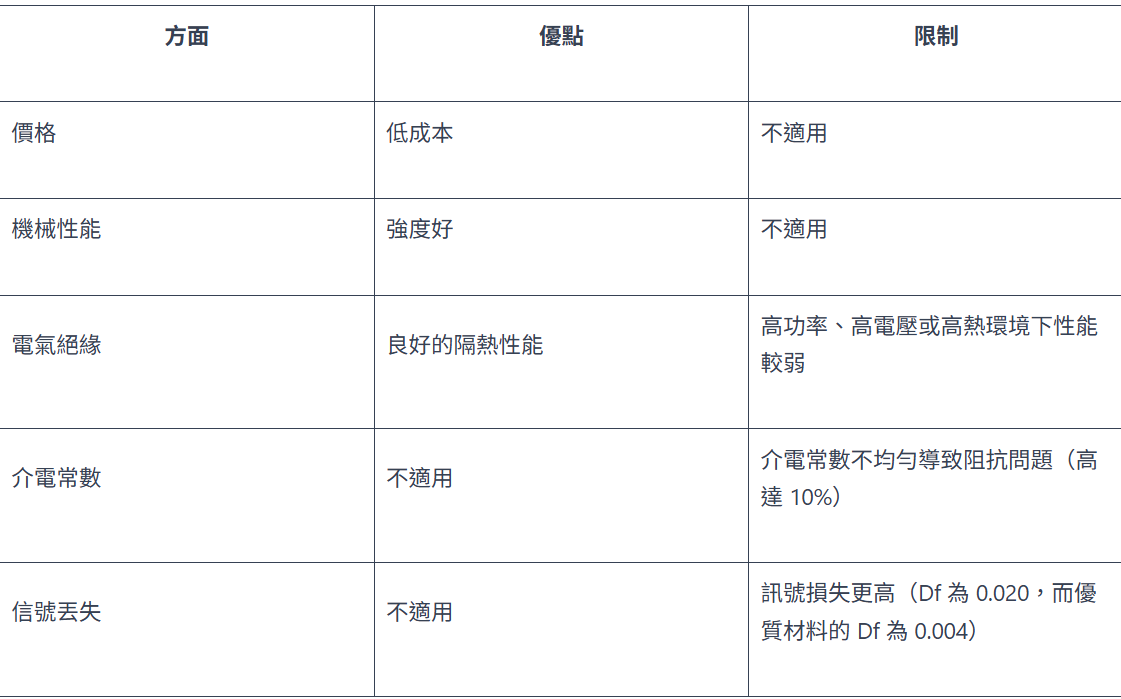
This is the current main battlefield!
Reading the above might make you eager to spec everything with top-tier materials. Hold on a second. Engineering is the art of compromise. Here are survival tips for R&D:
Many material datasheets list the Dk on the first page measured at 1 MHz (e.g., Dk=4.4).
Do not trust this!
Your circuit runs at 10 GHz, where the Dk might have dropped to 4.0. If you calculate impedance using 4.4, your manufactured board's impedance will be too high (e.g., 55 Ohms), leading to excessive reflection.
Correct Action: Flip to the back and find the "Dk/Df vs. Frequency" chart. Use the value corresponding to your operating frequency.
If you build the entire board with Rogers, the procurement department will hunt you down.
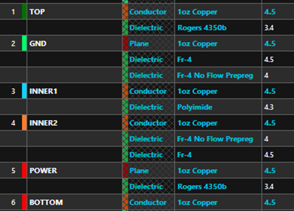
The smart approach is "Hybrid Stackup."
This is like wearing a suit jacket with shorts for a video call—spending money only where it's visible. However, be aware of the CTE (Coefficient of Thermal Expansion) mismatch; if the difference is too large, the board might warp during reflow soldering. This requires coordination with the PCB fab's capabilities.
Besides Dk/Df, there is a hidden killer called "Copper Roughness."
To make copper foil stick to the resin, the surface is usually roughened like mountain peaks (teeth). However, for high-frequency signals, current flows only through a very thin layer on the surface (Skin Effect).
If the copper is too rough, the current has to climb over mountain peak after mountain peak. The path gets longer, resistance increases, and loss spikes.
So, when buying top-tier material (M7), remember to pair it with HVLP (Hyper Very Low Profile) copper foil. Otherwise, it’s like putting off-road tires on a Ferrari—it won't go fast.
While Japanese (Panasonic) and American (Rogers) brands have high prestige, Taiwan's local giants TUC and ITEQ have made rapid progress in recent years. Their TU-883 or IT-968 series can already compete with M6 in many high-end applications, often with better lead times and costs. When evaluating a Second Source, they are definitely worth considering.
In the era of high-speed circuits, Layout Engineers can't just draw lines, and Hardware Engineers can't just read schematics. We must possess "Material Intuition."
The next time you look at a perfect eye diagram on the oscilloscope, or when your product smoothly passes PCIe Gen5 certification, don't forget to thank those silent Low Dk/Df molecules inside the board—and thank yourself for insisting on choosing the right material.
Would you like me to help you draft a specification sheet comparing specific materials (like Megtron 6 vs. TU-883) for your current project?
