June 14, 2026
Many R&D engineers have encountered this situation: the schematic is fine, the ICs have been verified, and the firmware runs, but the board just won’t connect. After switching to a new batch of components and making another prototype, it mysteriously starts working again. The problem often lies not in the components, but in those seemingly ordinary copper traces. When signal edge rates fall below 1 ns or the operating frequency exceeds 100 MHz, the traces on the PCB are no longer simply “wires,” but transmission lines. The biggest enemy of transmission lines is discontinuity in characteristic impedance.
The moment a signal jumps from one impedance value to another, a reflected wave is generated at the interface. This reflected wave travels back and superimposes on subsequent signals, resulting in a distorted waveform at the receiver.
Symptoms you'll see in practice:
If your design includes DDR, HDMI, PCIe, USB 3.x, Gigabit Ethernet, RF, or 5G mmWave, impedance control is mandatory – not a “nice to have”.
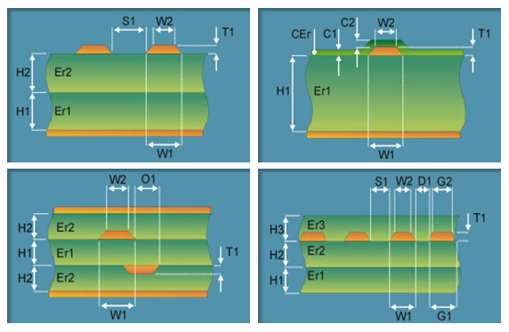
Many people think “trace width determines impedance” – that is a typical oversimplification. The real critical variables are four:
These four parameters together determine the final characteristic impedance of a trace. The Layout engineer can only control a part of them; the rest is in the hands of the PCB fab.
When placing an order with a PCB fab, you face a choice:
You only tell the fab: “L1 single‑ended 50 Ω, L3 differential 90 Ω, tolerance ±10%”. The fab then back‑calculates the stackup, trace widths, and dielectric thickness, and provides impedance test coupons for your acceptance. Responsibility lies with the fab.
You lock down the material, trace width, and dielectric thickness yourself, and the fab simply follows your specs. If the impedance falls outside the target, or shifts due to lamination tolerances, you have no right to ask the fab to redo it. Responsibility lies with you.
For the vast majority of teams, Option A is the sensible choice. Unless you have been working with a fixed fab for many years and know their specific material part numbers and lamination characteristics inside out, there is no reason to take on process uncertainties yourself.
The fab’s CAM engineer will perform final trace width compensation. If impedance traces use the same width as ordinary signals, the CAM cannot tell them apart.
Solution: Explicitly annotate the net class and target impedance values for impedance‑controlled traces in the fab notes, together with impedance test coupons. If you want to differentiate by trace width, you can make the impedance traces slightly different (e.g., ordinary signals 5 mil, 50 Ω traces 4.9 mil or 5.1 mil), but the fab note annotation is the reliable way for CAM recognition.
High‑speed signals require a continuous reference plane for return current. If the GND plane is split or interrupted by voids directly under the signal, the return path is broken – the result is skyrocketing EMI and severe crosstalk.
Solution:
Differential pair length matching is a basic requirement, and there are two levels: intra‑pair skew (within a pair) is usually more stringent than inter‑pair skew (between pairs); they should not be confused. Where you place the serpentine routing makes the real difference.
Core principle: Compensation should be placed near the source of the mismatch, not arbitrarily inserted into a straight section. When differential pairs change layers, each segment before and after the layer change must be individually length‑matched – do not rely only on the total length.
Many managers treat Signal Integrity (SI) as a “technical problem” and throw it over the wall to the R&D team. But for B2B manufacturing, the value of impedance control directly ties to the P&L:
As we enter the era of PCIe Gen5, DDR5, and 112G PAM4, impedance control must be a core consideration from the very beginning of design. Every link – from stackup planning to fab collaboration – must be aligned.
If your team is facing challenges with high‑speed PCB stackup planning, impedance simulation, material selection consultation, or inconsistent prototype quality, feel free to reach out to us. Helping you translate engineering details into stable, mass‑production‑ready standards is what we focus on.
