Bends, Coverlay, Stiffeners, and Mating Thickness
Review flexible regions, supported areas, and connector requirements before prototyping.
A flexible printed circuit, or FPC, can conform to an enclosure, but its conductors, protective materials, and stiffened regions must still withstand assembly and operating loads together.
A complete FPC design needs more than copper layers and connectivity. It must explain where bending is allowed, how often it occurs, which regions need support, and the finished thickness held by the connector.
If these conditions remain only in mechanical drawings or verbal discussions, fabrication and assembly teams may work from different assumptions. Review the following six items before prototyping.
Forming a circuit during installation and leaving it in place differs from repeated movement during product operation.
Bend performance depends on materials, copper layers, local finished thickness, radius, and use conditions. Online rules expressed as multiples of board thickness are preliminary references only when their applicable conditions are understood; they do not guarantee flex life.
Document:
Evaluate radius together with the actual stackup and validate representative samples under realistic use conditions.
Technical reference: Minco: Flex Circuit FAQs
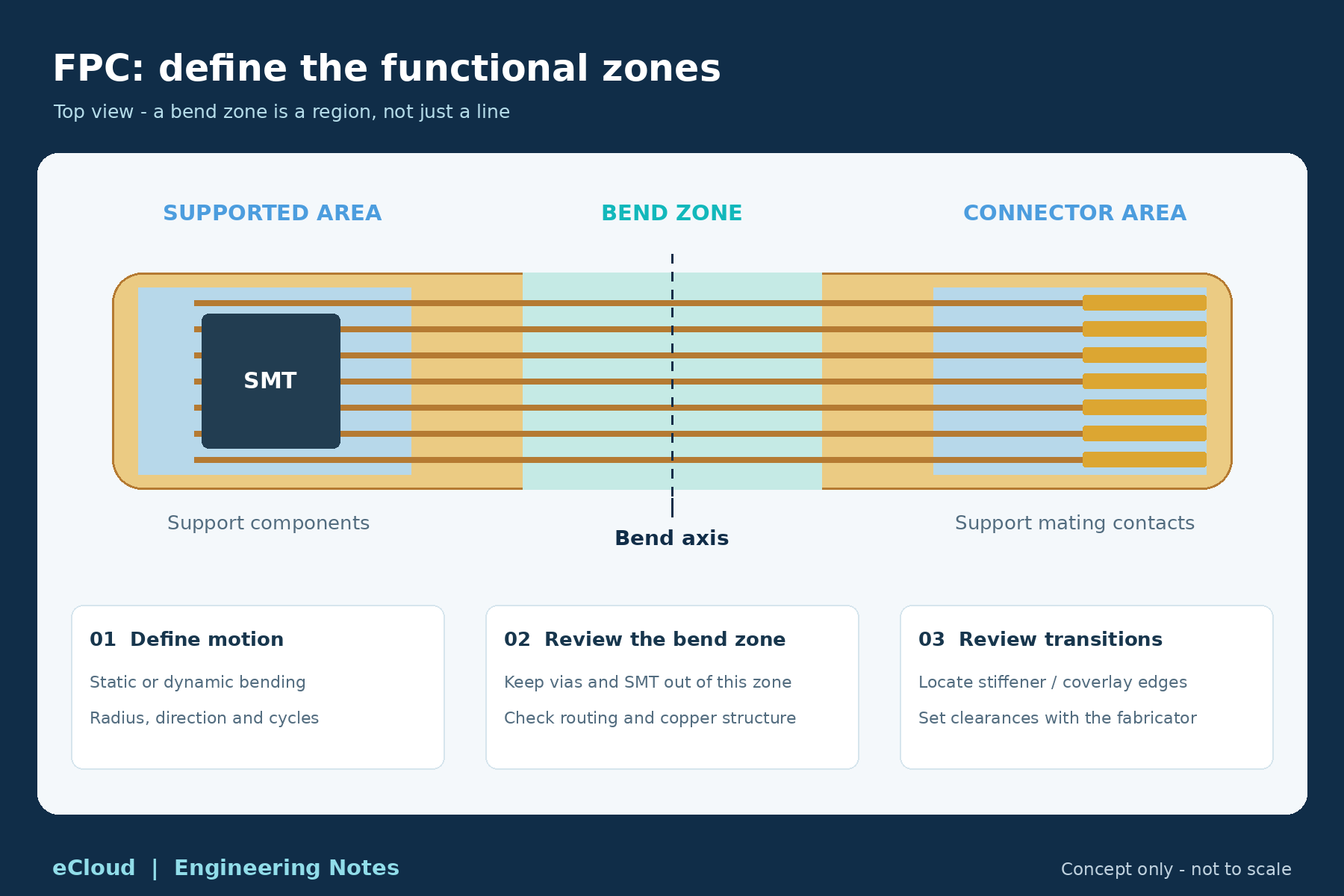
A single bend line does not describe the entire region subjected to bending.
Preferably keep components, vias, and structures that create localized stiffness or abrupt cross-sectional changes out of the bend region. Review conductor-width transitions, protective-material openings, and other discontinuities against the loaded area.
Technical reference: Minco: Designing a Flex Circuit for Flexibility
The boundary between stiffened and flexible regions also matters. Components close to the boundary, conductor-width changes at the boundary, and nearby coverlay-opening edges should be reviewed.
Required clearances depend on construction and process. Mechanical, layout, and fabrication teams should work from the same region-definition drawing.
Technical reference: Fujikura: Flexible and Rigid Section Design
Coverlay is a common protective material for flexible circuits. A typical construction combines polyimide, or PI, film with adhesive to cover conductors while leaving required contact or soldering areas exposed.
Material reference: Qnity: Pyralux LF Coverlay
Review more than nominal opening dimensions:
For fine-pitch assembly areas, discuss suitable flexible solder mask or combined-material approaches with the fabricator. Confirm bending suitability and transition details rather than transferring rigid-board solder mask settings directly.
Technical reference: OKI Electric Cable: FPC Materials and Design Guidance
Stiffeners can support component areas, assist assembly, or establish thickness at a connector interface.
Select PI, FR-4, or metal stiffeners according to stiffness, thickness, insulation, and assembly requirements rather than treating material names as quality grades.
Fabrication data should identify:
A stiffener adds local support, but its end also creates a structural transition. Overlay stiffener and bend drawings during review so boundary issues are not missed.
Construction reference: Fujikura: Stiffeners and Region Boundaries
Obtain the connector’s full part number and recommended mating drawing before selecting the FPC terminal construction.
For example, Hirose’s official information for FH67-20S-0.5SV(01) specifies a 0.3 mm FPC/FFC thickness. This applies to that model, not to every connector.
Specification example: Hirose FH67-20S-0.5SV(01)
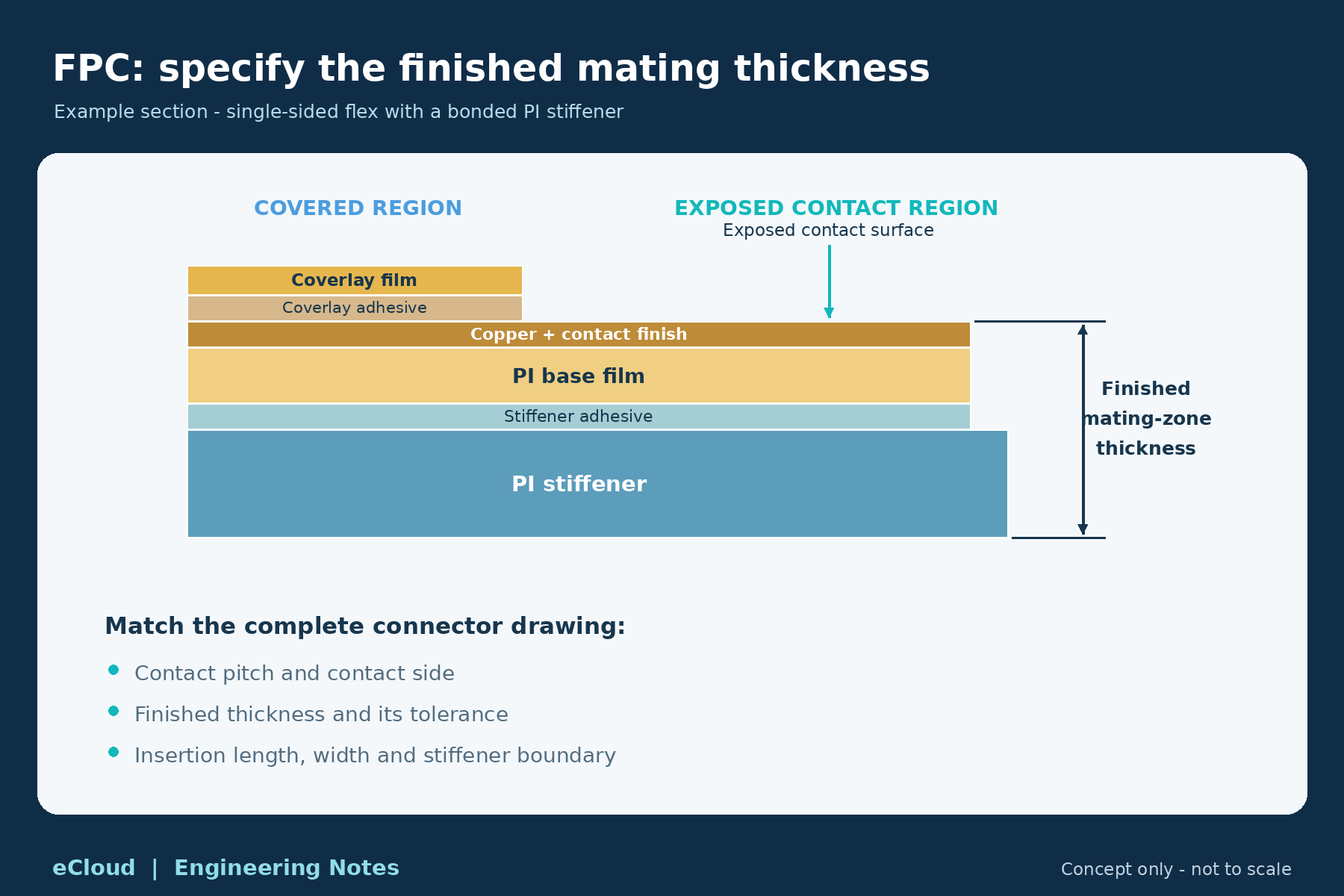
Calculate terminal thickness from the substrate, copper and finish, adhesive, and stiffener materials actually present in the insertion region. Whether coverlay extends into that area also affects the local construction.
Specify the finished thickness and tolerance of the identified region. Confirm contact orientation, terminal outline, effective contact length, and stiffener extent.
Specifying only the stiffener material thickness can still leave design and fabrication teams with different interpretations of the finished thickness.
Alongside Gerbers and drill files, provide:
Explicitly identify any via filling, special interconnections, or shielding films so process feasibility can be reviewed first.
Prototype validation should include actual mating and installation. Check continuity, contact condition, and function before and after bending as required by the product. Repeated-motion applications also need an appropriate life test.
Passing an electrical test and meeting a specified flex life are different validation items and need separately defined acceptance criteria.
Effective FPC design and prototyping translate mechanical motion into clear regions, stackups, and dimensional requirements.
Identify where the circuit bends, where it needs support, where copper must be exposed, and which local thickness the connector holds. Fabrication and assembly teams can then work from the same conditions.
For an eCloud FPC prototype inquiry, provide Gerbers, fabrication requirements, the stackup, stiffener drawings, and quantities. Include connector mating information and bending conditions to support feasibility review and identification of missing information.