M8/M9 High-Speed PCB Series | Part 1
Translate resin, glass and copper requirements into a material specification before prototyping.
When a high-speed PCB project reaches prototyping, R&D teams often encounter a familiar question: the simulation already uses a low-loss material, so why does the fabricator still need to confirm glass style, copper foil, resin content and stackup?
The reason is that electrical and manufacturing performance depend on the complete material construction. An “M8/M9-class” designation or a single Df value does not fully define the board to be manufactured.
Material selection should translate channel requirements into a specification that can be procured, fabricated and verified after prototyping.
When discussing M8/M9 high-speed materials, first establish whether the term refers to a particular product series or a market shorthand for a loss category. Similar class labels do not establish that materials from different suppliers are interchangeable.
Even one product series may offer different glass and construction options. For example, the MEGTRON 8 datasheet distinguishes ultra-low-Df glass and low-Dk glass versions, with different corresponding properties.
Before releasing a fabrication order, confirm at least:
The material name is the starting point. The agreed stackup and fabrication data must define the final construction.
Reference: Official MEGTRON 8/8S datasheet
 Resin contributes to dielectric loss and influences curing, flow, moisture behavior and hole preparation. “Low polarity” alone does not establish poor adhesion, and low-loss laminates should not all be treated as the same resin system.
Review the actual product documentation and processing guide. Similar resin-family descriptions do not establish identical formulations, fillers or processing responses.
A glass-and-resin composite is not completely uniform at the microscopic scale. In a sensitive high-speed differential pair, the two traces may experience different propagation delays if they encounter different distributions of glass and resin.
Constructions such as spread glass can help mitigate the glass-weave effect. Their effectiveness still depends on the material and trace position and orientation; they do not guarantee the elimination of skew.
High-speed signal loss also depends on copper foil profile and surface treatment. If the copper conditions differ, an insertion-loss difference cannot be attributed entirely to resin Df.
Low-loss material selection therefore requires confirmation of resin, glass and copper foil together.
Reference: Spread glass and low-profile copper in high-speed materials
Dielectric constant, Dk, and dissipation factor, Df, are important. However, a typical datasheet value is not necessarily the appropriate input for the impedance calculation of every layer.
Before comparing values, check the test frequency, method, specimen construction, resin content and moisture-conditioning conditions. Ranking numbers obtained through different methods does not establish which material is more suitable.
Impedance design should use the fabricator-confirmed stackup and an applicable design Dk. Changes to glass style, resin content or dielectric thickness require a review of the calculation inputs, even within the same material series.
Likewise, 800G or 1.6T describes a system or interface rather than a complete laminate requirement. R&D teams also need to specify lane rate, modulation, trace length and the allowable channel loss.
Low loss does not necessarily require an entirely new fabrication process. It also does not establish that existing parameters can be reused without adjustment.
When the material construction changes, the fabricator must confirm resin fill during lamination, dimensional behavior, drilling and hole preparation. If layer count, board thickness, copper thickness or hole depth also increases, the manufacturing challenge may come from the construction itself rather than the material class alone.
A substitution review should therefore cover both electrical suitability and the fabricator’s processing basis for the material and a comparable construction. Material-supplier processing recommendations are generally starting points; the fabricator must validate the results.
Reference: Low-loss material processing guide
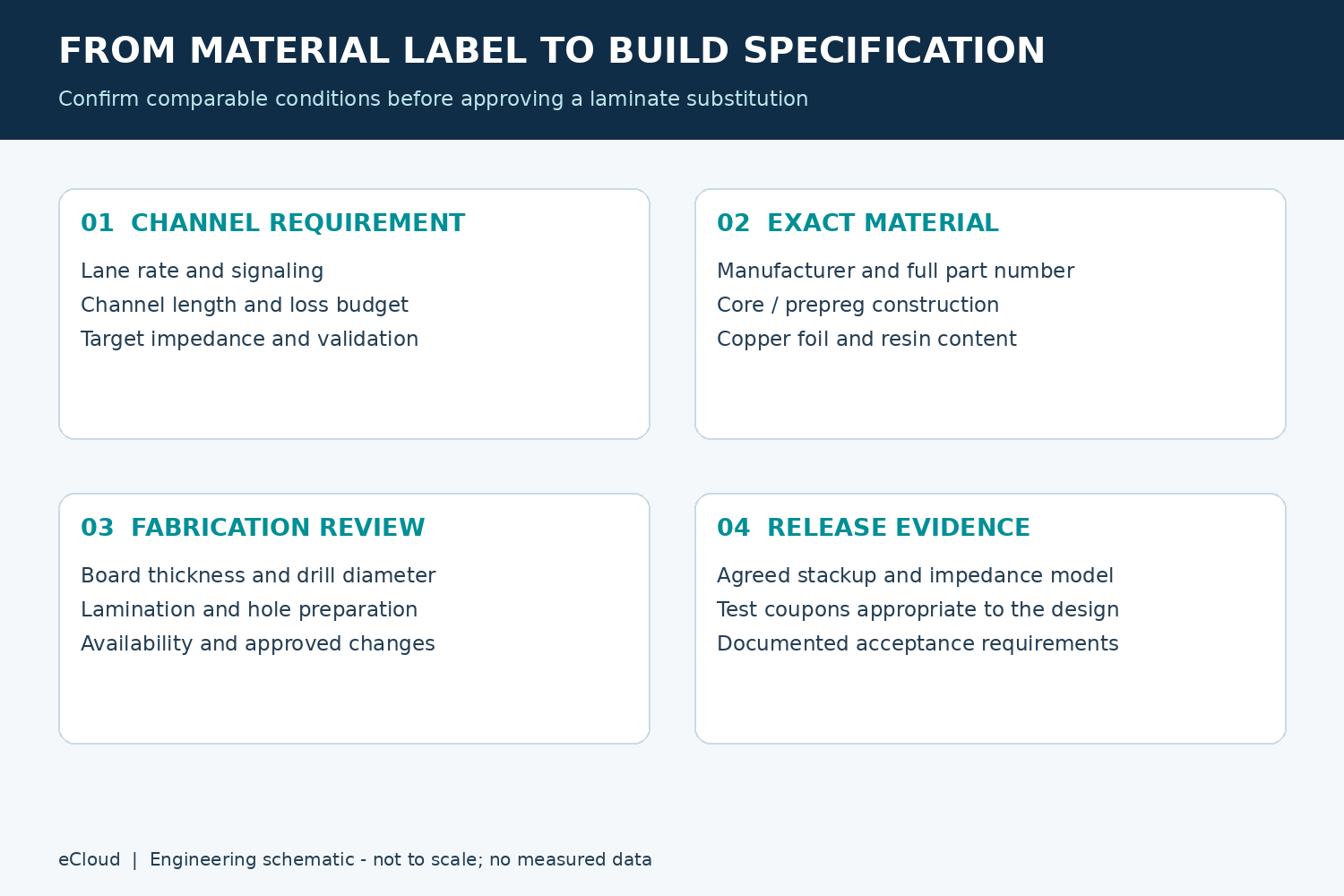
If material selection is still open, provide the target requirements and candidate materials first so that the engineering discussion starts from comparable conditions.
M8/M9 high-speed PCB material selection should connect channel loss, actual material construction and fabrication requirements. Confirming all three helps align simulation, procurement and finished-board verification.
For a high-speed PCB prototype, provide eCloud with the Gerber files, candidate materials, stackup and impedance requirements for discussion of material and fabrication conditions. Any material substitution should receive written approval before production.