Connecting MCU, Sensing, Power, and PCB Design
Plan processing resources, input quality, and testability from the first product board.
Voice control works on the demonstration table, but starts missing commands after the board is installed in its enclosure and a motor is switched on. A model runs on the development board, yet encounters memory and power limitations on the product board.
 These are hypothetical situations, but they highlight an important validation question: can the model, electronics, enclosure, and operating environment work reliably together?
For Taiwan’s hardware teams, turning fabrication and circuit design expertise into application value requires planning models, firmware, PCBs, and testing together from the beginning.
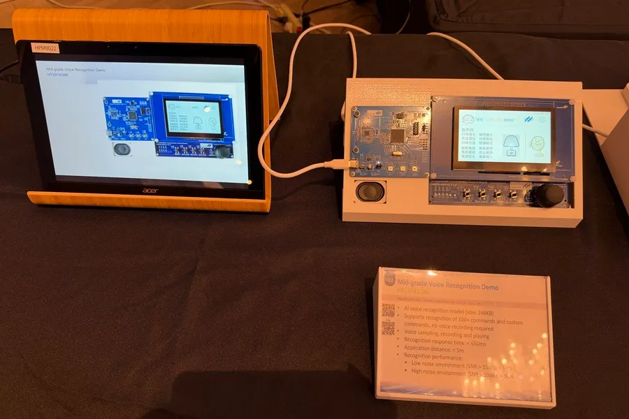
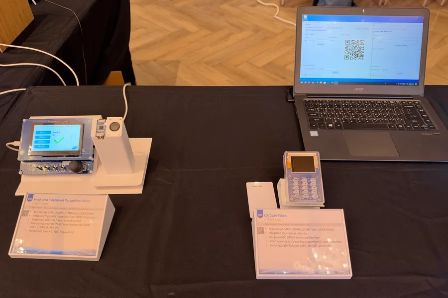
At its 2026 new product presentation, Holtek showcased voice recognition, TinyML development platforms, and fingerprint recognition applications, illustrating the extension of microcontrollers, or MCUs, into specific intelligent tasks.
Such offline applications typically perform bounded recognition or decision tasks on the device, such as recognizing a defined set of voice commands. Their processing and memory requirements differ from those of large language models supporting open-ended conversations.
QR Code decoding, fingerprint processing, and neural-network inference should also not be treated as identical workloads. Accelerator suitability depends on the supported tasks, data formats, and software tools.
Application background: Holtek’s 2026 New Product Presentation
 Comparing only clock speed and model file size can underestimate system requirements.
Google’s microcontroller deployment documentation notes that a model must fit alongside the rest of the application and use supported operations. Model complexity also affects processor workload.
Implementation requires working memory for inputs, outputs, and intermediate calculations. LiteRT for Microcontrollers, for example, uses a preallocated tensor arena whose required size depends on the model.
Technical references: Model deployment constraints and Runtime memory allocation
Before prototyping, document:
If external memory is required, plan its pins, interface, routing, and board area at the same time.
An offline voice product needs more than a microphone connected ahead of the model.
For a bottom-port MEMS microphone, sound enters through an opening in the PCB. The enclosure opening, sealing arrangement, and acoustic path can also affect final acoustic performance.
Technical reference: TDK InvenSense Microphone Mounting and Connection Recommendations
After bare-board recognition testing, repeat the assessment with a representative enclosure, acoustic path, and mounting position. Cover actual operating distances, background sounds, and noise from the product’s own fan or motor.
PCB and assembly documentation should identify acoustic openings, lands, solder mask, and stencil requirements. Confirm hole dimensions, tolerances, and plating status against the selected component’s recommended drawings.
MEMS microphones also have cleaning and rework restrictions. Communicate the component-specific instructions to the assembler to avoid port contamination or damage from cleaning processes.
Process reference: TDK InvenSense MEMS Microphone Handling and Assembly Guide
Inference, displays, communication, and actuators may start at different times. If voice control shares a supply with a motor, observe the MCU supply, reset status, and recognition results during motor startup.
Holtek’s hardware development guideline identifies power, grounding, decoupling, clocks, and reset as fundamental design items. It also directs designers to the selected device’s documentation for model-specific requirements.
Technical reference: HT32 MCU Hardware Development Guideline
Practical checks include:
Battery-life evaluation should use the actual duty cycle, including sensing, inference, communication, and standby.
The label “AI” does not determine PCB layer count, material grade, or via structure.
Review the MCU package, sensors, external memory, and communication interfaces before selecting layers, reference planes, and fabrication processes. Where controlled impedance is required, confirm the targets, stackup, and relevant traces together.
Before releasing a product board, check:
Development-board headers and module cables also need formal mechanical, assembly, and service arrangements. Reducing the board outline alone does not complete productization.
Recognition failures may originate in input quality, acquisition, model decisions, or downstream control. Debugging becomes difficult if the only available message is “pass” or “fail.”
Provide the first product board with:
For a voice-controlled appliance, for example, test both unintended activation without a command and missed recognition of valid commands. Then check whether motor operation changes the results. This is a test-planning example; acceptance thresholds must come from product requirements.
The value of an edge AI product depends on task completion, user experience, and demonstrable reliability.
Model developers need realistic sensing conditions. Hardware teams need memory and workload requirements. Manufacturing and test teams need clear drawings, revision control, and acceptance criteria. Aligning these inputs early can help reduce repeated board revisions.
For an edge AI PCB prototype inquiry, provide eCloud with Gerber files, fabrication requirements, the stackup, and quantities. Identify sensor openings, mandatory materials, and special processes to support fabrication review.