As AI Hardware Accelerates, Engineering Alignment Must Start Earlier
From TPCA’s industry outlook to the engineering value behind material, stackup, and validation decisions.
In the morning, your manager forwards a headline: “Taiwan’s hardware industry enters a golden decade.”
In the afternoon, your PCB supplier emails: “The specified material has a long lead time. Would you accept an alternative?”
At the project meeting, the prototype deadline stays the same.
This hypothetical situation captures a difficult gap in hardware development: industry opportunity can be discussed over a decade, while the current PCB revision must complete validation within a fixed schedule.
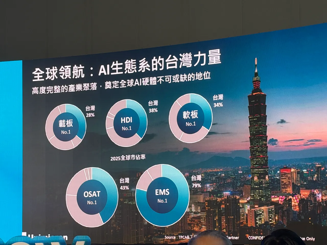
In his TPCA Show opening address, Unimicron chairman Chien Shan-chieh discussed AI-driven hardware opportunities alongside three bottlenecks: high-speed interconnects, efficient power delivery, and thermal management. He also highlighted material and equipment supply challenges. Background: TPCA’s official event coverage
Viewed through an R&D engineer’s daily work, the address raises a practical question: as hardware demand accelerates, are teams also scheduling the engineering work needed to support it?
However impressive a chip’s specifications may be, the product still needs to deliver signals, maintain stable power, and remove heat.
 At board level, those needs become specific trade-offs: signal-layer assignments, reference planes, material selection, space allocation for power and cooling, and which processes justify additional cost.
This is where R&D engineers can feel the pressure.
Each requirement may be reasonable on its own. On the same PCB, they can interact. Allocating another high-speed channel may constrain power layout. Changing dielectric thickness may require recalculating trace widths. Adding a fabrication process also requires reviewing manufacturing and validation schedules.
Hardware engineering creates value by making these conditions work together.
When a high-speed channel has problems, an obvious question is: “Didn’t impedance pass?”
Characteristic impedance is only part of channel evaluation. Reference planes, return paths, via stubs, and connectors also require attention. TI’s high-speed interface layout guide addresses these layout and interconnect issues separately. Technical reference: TI High-Speed Interface Layout Guidelines
For R&D engineers, the essential question is whether the analysis still represents the board that was actually manufactured.
If material, dielectric thickness, or trace width changed, was the original model updated? If manufacturing supplies impedance results, which questions can the measurement locations and test structures answer, and which system conditions still require validation?
Defining those boundaries makes a passing report useful evidence for debugging.
Material substitution may appear to be a purchasing issue, but the decision often returns to the R&D engineer’s desk.
Tg is glass transition temperature. It does not independently describe a material’s electrical properties or complete thermal reliability. Depending on the application, substitution assessment should also compare dielectric constant, Dk; dissipation factor, Df; thermal expansion; and other relevant conditions. Electrical values also require attention to frequency and test method. Material reference: Isola Product Selection Guide
Consider a hypothetical material substitution on a high-speed board. Even if finished thickness and impedance targets remain unchanged, the team should reassess whether the stackup and channel loss still meet requirements.
“Can we substitute it?” therefore deserves three separate questions:
Writing out these questions allows purchasing, R&D, and manufacturing to make a shared decision. Otherwise, “equivalent material” can carry unevaluated risk into the next stage.
Consider another hypothetical situation: the boards arrive on time, but instability appears during bring-up—the initial power-on and functional validation.
 The team investigates power, firmware, assembly, and signals. Days later, it discovers that manufacturing used a different stackup revision from the one used in analysis.
The additional work extends beyond rerunning a simulation. The team must establish the differences, rebuild its basis for judgment, and potentially schedule new prototypes.
A worthwhile PCB prototyping outcome is therefore a board that corresponds to the design conditions and supports validation.
When a manufacturing change is raised before production, engineers still have choices. When the difference emerges after delivery, those choices often narrow to additional validation or another revision.
Applying Chien’s emphasis on supply-chain collaboration to product development suggests a concrete starting point: complete the necessary manufacturing feasibility checks before critical layout conditions are locked.
Earlier design for manufacturability, or DFM, review gives teams more room to adjust.
Before releasing the next revision, review these items together:
These checks have a cost. Including them in the plan makes it possible to judge whether a delivery commitment is executable.
At a project review, an error that causes rework is easy to see. A problem prevented early may leave little visible record.
A manufacturing limitation identified in advance, an unapproved substitution stopped before production, or a clear revision comparison can preserve time for subsequent validation.
These contributions deserve to be recorded as project outcomes and included in schedule and resource planning.
Taiwan’s hardware golden decade will ultimately depend on engineers turning opportunity into products that operate reliably, can be manufactured, and can be delivered. For teams developing AI hardware and PCBs, the practical goal is to give design decisions, manufacturing alignment, and validation enough room in the project.
The next time someone asks, “Can this revision be faster?”, the team can answer together: which conditions are already confirmed, and which decisions must be completed first?
If your project is evaluating PCB materials, stackup, or fabrication processes, share the Gerber files, fabrication specifications, impedance requirements, and target schedule with eCloud. Clarifying the manufacturing conditions first establishes a clear basis for subsequent prototyping and validation.